Analog data coming from DCS fluctuaing

jainil2210

Member
Join Date
Oct 2009
Location
vadodara
Posts
28
Hello ALL.

One strange problem I am facing in my 1769-L33E controller PLC is

All the data coming from DCS (Analog-4-20mA) in my PLC analog input card (1769-IF8) cha no: 4,5,6,7 are fluctuating in the range of +/- 2.5 %
means If I am soucing/DCS is giving 10% output , I can see data hunting in the range of 7.5 to 12.5 % of the full scale range
This is only happening to data coming from DCS. rest all the data coming from transmitters are fine in the same module ch: 0,1,2,3
I also checked mA at DCS with the help of multimeter in series and mA is showing steady, not fluctuating, it is only happening to PLC/HMI display
Wiring is also done as per standard engineering practice where 24V DC is looped by DCS analog output card and not by PLC analog input card for those channel
FYI, same module is having transmitters input in ch:0,1,2,3 and showing fine, Ch: 4,5,6,7 are coming from DCS which are fluctuating.

I there anything need to be taken care in programming of PLC for this or module configuration of IF-8 to be checked?
Please advise.
 
Is the input wired in isolation?? seem to remember that the isolated inputs can become unstable if the voltage differential to another input is > x

I had an instance a few years ago where I had inputs demonstrating similar behavior on an IF8, and ended up grounding all the DC supplies and tying loops to the analogue common to fix...
 
Hi Lemming,

Could you please elaborate further?
I am not sure what is to be done from your post.

Yes inputs are used with isolators at DCS end.
In you post you are saying that input will become unstable if the voltage diff to another input > x. what is this "X" value?
what you trying to say by "ended up grounding all the DC supplies and tying loops to the analogue common to fix"

Awaiting for your valuable reply.
 
The 1768-IF8 is an eight-channel non-isolated input module.

Generally if your instruments will not have the same DC power supply or be referenced to the same DC potential, you should use an isolated-channel input module or provide per-channel isolation devices.

This is so that differences in the DC common between different channels do not affect the other channels.

We would have to see your wiring diagram to comment on how the system is wired.

How quickly is the data "varying" on the channels connected to the DCS ?

This is the sort of signal troubleshooting problem for which an oscilloscope is very valuable.
 
Yes, Understood now,
Yes, I can see this possibility
For range hunting please see below

Remote IGV signal fluctuating between 7.8 to 12% for 10% command given from DCS
Remote BOV signal fluctuating between 97 to 102% for 100% command given from DCS
Remote set point signal fluctuating between 6.2 to 7.2 Bar for 6.5 Bar set point command given from DCS.

I am not able to attach diagram here , i don't know why

But I can give you a description

for all 2 wire transmitters and signals coming from DCS (2 wire)connection of + and - are landed to 1 TB, from TB -ve is wired to I in 0+
All common in module are grounded
All the 24VDC are looped and grounded

For signals coming from 4 wire source,

2 wires are wired to I in3+ and I in 3- (number indicates channel number)

Hope this will help you to get wiring
 
Assuming your are not using sourcing analogues (think thats what you call it when the throttling is done on the negative side of the input ???) I'd tie all my I- to a common ground to see if the issues go away...

X = 10V, but stood for couldn't remember :)

Capture.JPG
 
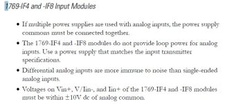
The 1769-IF4 and 1769-IF8 modules both support either single-ended or differential inputs, but the DC Commons of all circuits need to be within 10V of one another.

The 1769-IF4I, by contrast, is "isolated" channel-to-channel and channel-to-backplane by circuits that can are isolated to 30V, rather than 10, and can withstand temporary voltage differences up to 500V.

A nice concise summary of CompactLogix analog specifications is in this manual, a "Technical Data" that summarizes a bunch of information that is otherwise spread around in User Manuals and Installation Instructions:

http://literature.rockwellautomation.com/idc/groups/literature/documents/td/1769-td006_-en-p.pdf

If I were the OP I would try to figure out the frequency of the induced signals, so he can figure out if this is "drift" or "noise" or something else.
 

Similar Topics

I cannot add SLC500 analog input tag (I: 8.3) to EZSeries Touch Panel Editor (V 5.3). I used all the listed tag datatype but it all says "Invalid...
Replies
3
Views
68
I have a strain gauge attached to a load cell. The strain gauge is wired into an analog channel on a ControlLogix 1769 controller at +/-10V. How...
Replies
6
Views
2,422
Wondering if anyone has any suggestions that could help me out. I am looking for recommendations for hardware for an upcoming project. I am...
Replies
3
Views
2,026
I am noticing odd behavior with a CompactLogix PLC I have here as a test unit. I have absolutely no I/O wiring on this unit, I just use it to...
Replies
2
Views
2,081
Hi all, I need to collect the analog data like 4-20, mV signal or any digital count from FF based communication instruments for calibration...
Replies
1
Views
1,890
Back
Top Bottom