AB Micrologic RSS file

Snow Dog

Member
Join Date
Jan 2004
Location
Puyallup, Washington
Posts
9
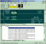
I have been trying to write a program for a AB Micrologic 1500 to start up a chipper / blower system, and am getting to the point of frustration. I have had no formal training, but I understand PLC and thier functions. It seemed fairly simple until I started trying to make it "better". I have attached a zip file with 2 programs. One is very simple, and the other (mine) that I am having problems with. Any help would be appreiciated.
 
I don't know the problem. I have no way to test it other than looking at the ladder. In my mind it should work, but there are errors in the ladder that I can't figure out. Maybe I am over looking something simple. I just don't know.
 
Use the Bit Level!!

You need to specify logic the bit level, or in other words....
In ladder line 20 as an example....

Your logic uses a N/C T4:11, but does not specify WHAT you are monitoring....

Are you looking for T4:11/DN or T4:11/TT, or T4:11/EN bits?

Instruction bits: 13 = DN (done)
14 = TT (timer timing bit)
15 = EN (enable bit)

Once you specify these bits the program will verify properly. As for your logic, I have not spent any time looking at your possible faults.

I try to develop using State Logic, which is a more concise way of programming.

Let me know if you require any additional assistance.
 
To write an address for a timer use this example:

T4:0/dn

To delete unused lines (rungs) highlight on the left, press the delete key on your computer.

Attached is a copy of your file with the verify errors cleared.
I did not check the logic for correctness, use for information purposes.
 
Version???

What version of RSLogix500 was your file written in?

I am stuck with version 4.5 (I can upgrade at my own expense) & when I try to open your file it crashes RSLogix500 with a file format error.
 
Snow Dog said:
I have had no formal training, but I understand PLC and thier functions.

That's a start. However, since you're working with A-B products, you need to understand A-B's nomenclature - specifically in this case, the function of delimiters.

The timer you're trying to use lives in an area of memory called a file. This file has been defined to hold timer structures. It is the fifth file in the processor's memory area, hence the term "T4", numbering from zero. If you wanted a new group of timers set aside to handle some function of your machine you could create a new file called T15 which would also hold only timers.

Now, within this T4 file are individual timers, with preset words, accumulated value words, and control bit words. To examine the contents of the elapsed time for the first timer in this file the address is T4:0/ACC. The ':' delimiter separates the file address and the specific timer address. The '/' delimiter separates the timer and the particular part of the timer you're interested in. To check if a timer is timed out, that is, is the done bit turned on(?), the address is entered as: T4:0/DN. As in,

T4:0/DN
-----] [----


Counters are addressed pretty much the same way.

Hope this helps.
 
Last edited:

Similar Topics

Dear all, Currently i'm working with micrologic 1400 cpu and Temate G5 Controller. I plan to communicate micrologic with temate using...
Replies
0
Views
399
Hi All, I am looking for Modbus Communication Address register details for Schneider ACB Micrologic 6.E0.. We are trying to communicate with AB...
Replies
0
Views
377
I had a question regarding the Micrologix 1400 AI/AO's. I have a 4-20mA AI wired to an input channel (I:3.0) and I am moving that value to an...
Replies
5
Views
1,069
Hello Ken Roach, Thank you for your quick reply , As informed earlier i want to read P&F Sensor data on Micrologic 1400 series B using MSG...
Replies
17
Views
5,791
So I have to encoders with A,B and Z pulse 360 encoder wired up to A0+, B0+ and Z0+ and the - pulses wired to common 24vdc. I can see the inputs...
Replies
0
Views
1,037
Back
Top Bottom