Timing Diagram for RLL

OkiePC gave you the best answer

Welcome to the site But please read the answers

This is from his reply

ton.GIF
 
the TOF is what is called an Off Delay timer
it times out to operate a contact after the power is removed
 
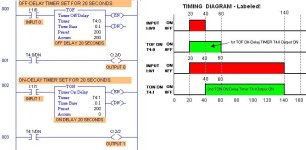
I went through 4 years of engineering college and most timimg diagram examples in the books and drawn by the professors never had labels so that you could not tell when the Inputs were ON and when the Timer finished timing and was ON. A little box can mean anything if there are no labels. Where is ON and where is OFF? I still think that a timing diagram without labels is like a PLC program without comments.

Here is a timing diagram with labels.

Timing Program & Timing Diagram Examples.JPG
 
Last edited:
Hi Lancie,

Great example to show beginners the basics. You may want to correct the labels for the 2 x input devices though as some may get confused! (you have them as I:0 in one diagram and I:1 in the other!).

Not being picky...just trying to avoid needless questions!

Regards,

Rob
 
Sorry, but I cannot see where there is an error. There are two inputs, I:1/0 and I:1/1, and that is the way I labeled them in each of the two places that they occur. Perhaps you were looking at an earlier version?
 
Last edited:
it is one of those OOPS moments Lancie1
I:1/0 and I:1/1 is of course right for the program.....

look at the explanation diagram
I:0/0 and I:0/1

we all do it
 
I will admit that I'm easily confused, as l follow what Kidblue says if you are using TOF input I/1/0, timer diagram input shouldn't be I/0/0 to remove any confusion (why I/0/0 when that is CPU slot). Also being picky and to remove all confusion, if the TOF timer input I/1/0 should be ON at the start of the diagram or don't open it, at the same time frame as the delay, you would then see that the signal got removed then timed out for 20 sec before turning off.
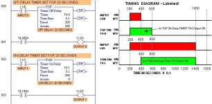
But all appreciation to Lance, l also agree timer diagrams should be easier to understand.
Me l look at time delays, the other way round. TON, Time- delay- ON. TOF, Time- delay- OFF.
 
All these comments reenforce the need for correct labeling on timing diagrams.

Also being picky and to remove all confusion, if the TOF timer input I/1/0 should be ON at the start of the diagram or don't open it, at the same time frame as the delay, you would then see that the signal got removed then timed out for 20 sec before turning off.
Sorry, I don't understand your comment. I carefully tested the TOF timer and it works as shown.

Timing Program & Timing Diagram Examples.JPG
 
Last edited:
Thanks for correcting the Inputs, I agree the TOF is working correctly as you describe, just to remove any confusion for students trying to grasp the concept , if the TOF I/1/0 time ON (true) was different to the delay time, then students would easily see when the signal becomes false and the start of the delay time to OFF (why have 2 identical times, when 2 different times could not confuse). I know l am being pedantic, but that said, l appreciate all your efforts and how freely you are with your experience and knowledge, all in an effort to improve ours. Thanks Lance
 
If the TOF I/1/0 time ON (true) was different to the delay time, then students would easily see when the signal becomes false and the start of the delay time to OFF (why have 2 identical times, when 2 different times could not confuse).
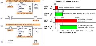
I suppose our thinking is different. If I did not know the differences between the timers, I would want to see how they operate when set to the SAME time. Why change the time, when then the students then will not know if the difference is caused by the time difference or the operational characteristics?

I think the time from 0 until the Input goes ON should have been something other than 20 seconds (maybe 10 seconds), because that does add an unnecessary confusion factor. The timing diagram shows that the total time that each type is ON depends on the timer setting AND the Input trigger ON time.

Timing Program & Timing Diagram Examples.JPG
 
Last edited:
Thanks Lance, professional to the T. Yes l can see were you are coming from with the identical times for both timers, l hadn't thought along those terms.
Students will be able to thank you, for giving clear instructions on the timing diagrams, answering how the timers work.
 

Similar Topics

Hi everybody, I am trying to illustrate a timing diagram for somebody. I always have been drawing on paper. I am wondering, is there any software...
Replies
1
Views
2,923
I am running a program on STEP 7's PLCSIM, and I want to create a a timing diagram of the I/O as the program runs. Currently to do this I use the...
Replies
1
Views
2,197
Hi my name is richard oneill and i have currently just started a course in plcs but am having trouble understanding the timing diagram as it wasnt...
Replies
3
Views
5,469
i need to design the PLC ladder diagram for 4-ways traffic light control. the timing for the lights are: R= red light for 30 seconds...
Replies
4
Views
7,132
Hello, I am struggling to figure out some logic. I have an analog pressure sensor coming into the PLC and would like to have multiple timing...
Replies
4
Views
150
Back
Top Bottom