Shut Down Key newbie//FANUC Logic

ericnovvak

Member
Join Date
May 2014
Location
Calgary
Posts
5
Hello all,

Another question from the newbie..

I am currently building a shutdown key for an oil and gas application based off of logic from a DOS6 Fanuc logicmaster program. Its proving to be a frustrating task as none of the contacts nor the coils have any descriptions. They are merely identified by numbers.

I have been toying around with the program (which is completely barbaric and antiquated to me) to try and differentiate which points are physical INPUTS and physical OUTPUTS compared to internal bits, or internal memory points, etc...

Is there a way to extrapolate this information from fanuc? I have scanned through the program to the best of my (limited) ability and see nothing.. Im afraid that I will have to dig up 25+ year old drawings and go page by page to figure this stuff out, so be fore I do that maybe one of you can help me out.

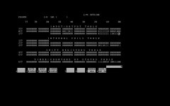
Ive attached a screen shot of the Display Reference Table and my assumption is that the 0 (zeros) denote an OUTPUT and the 1 (ones) are for INPUTS. When I hover over any specific point it tells me which I/O # it belongs to so if my assumption is correct I may be able to save SOME time, but if you know of better or easier ways (or completely different ways for that matter) I am all ears/eyes.

also, any tips/advice about shutdown keys in general would be greatly appreciated as well.

Thanks all in advance.
Untitled.jpg
 
Based on the I/O addresses, it looks like a Series One program. The Series One is still available from Automation Direct. Today it's called the DL305.
If you can locate an annotated copy of the program file your task will be a lot easier. If you opened a file it had a file extension of .LAD. Look for two additional files with the same filename but extensions .NAM and .EXP. Those will have the reference names and any rung comments.
You can't tell from an address whether it is an input or an output. The I/O addresses correspond to the slot location in the I/O rack. The slot closest to the CPU module is addressed as 000 through 007 for the first eight points. If there is an input module in the slot, address 000 is an input. If there is an output module in the slot, address 000 is an output. If there is a sixteen point module in the slot, the second 8 points are at address 100 - 107. Addressing is octal.
I'm not sure what you mean by "shutdown key".
Thanks for the reply Steve,

I guess to rephrase my question, what are the 1's and 0's in the display reference screen representative of?

Also, from photos taken from site it looks like after the CPU module there is (in order from closest to furthest from the CPU):

-8 point INPUT card
-16 point INPUT card
-16 point OUTPUT card

Which Fanuc addresses are associated to each of these slots? Im still a little unclear on how exactly you said they are allocated number-wise based on their slot proximity to the CPU module.

And as for what I mean by a 'shutdown key', as far as my understanding goes, it is a document that programmers use to reference the systematic shut down, energizing or de-energizing of specific physical outputs and which physical inputs are specifically triggering the action on the specified output. Like a control narrative, it is a reference tool to make sure that the plant is operating according to spec.

Thanks again.
 
Last edited:
I guess to rephrase my question, what are the 1's and 0's in the display reference screen representative of?
1 means true (On). Zero means false (Off). If the address is an input, 1 means there is current flow at the terminal and the PLC detects that current flow.
If the address is an output, 1 means the PLC program is commanding the point to be on.
The screen shot you provided was taken when the Logicmaster software was not communicating with the PLC (Offline) so the pattern of ones and zeros represents the states of the I/O at some time in the past when Logicmaster stored the states.

-8 point INPUT card closest to the CPU module, addresses 000 - 007
-16 point INPUT card next position left, addresses 010 - 017 and 110 - 117
-16 point INPUT card next position left, addresses 020 - 027 and 120 - 127
-16 point OUTPUT card next position left, addresses 030 - 037 and 130 - 137
-16 point OUTPUT card next position left, addresses 040 - 047 and 140 - 147
-16 point OUTPUT card next position left, addresses 050 - 057 and 150 - 157
 
Last edited:
okay thanks. I was more-so just curious if this software used its 1's and 0's as a reference for identifying which tags are inputs/outputs in the reference directory (which I was told by a co-worker might be the case) but if its just a capture from some old data then I guess it doesn't really serve me any good in that regard, but your explanation of the slots/points makes a lot of sense and while reading thru the fanuc manual I'm seeing a lot of similarities to what you're saying, so thank you. I still have a good amount of head scratching ahead of me but I think this gives me a good launching point.

Cheers.
 
The Series One is an old platform. It dates back to the early 1980s. I think there are two reasons why Automation Direct continues to sell it. First, because there are lot of them in service and they can still sell spare parts. Second, bragging rights. Who else can make the claim that they have a PLC model with that long a production history? The product brand labeled by GE Fanuc was manufactured by Koyo, the parent company of Automation Direct.
 
Unless you are only to document this system IMHO, it would make more sence to write your control logic from the ground up using a good sequence of operation for the process.
Whatever system you use will likely have more advanced functions and tools that should make the new logic better.
 
You're right, but I am only using the Series One logic for documentation purposes at this point tho. I believe the plant is doing a system upgrade so the SD Key is a necessary primary step in that process. Thanks
 

Similar Topics

I have a panelview plus 7,and often popup a messagebox"application servicesd.exe encountered a serious error and must shut down"I refreshed the...
Replies
0
Views
1,063
Hi, I need to upgrade the ups on the FactoryTalk Scada Servers. I have a primary server, secondary server and Historian server. 1) Is there a...
Replies
4
Views
2,572
This is slightly off-topic, but I figured I'd ask the community. I have an application where we're running a panel PC with Windows 7 Professional...
Replies
22
Views
7,411
Hi, I just experienced something strange. I connected a Field PG (PG/PC adress 0) on a profibus network to monitor something in the field. I...
Replies
16
Views
6,843
So I am wondering how many other troubleshooters force things on or write around things temporarily to get a machine running, then come back and...
Replies
36
Views
12,868
Back
Top Bottom