
You are using an out of date browser. It may not display this or other websites correctly.
You should upgrade or use an alternative browser.
You should upgrade or use an alternative browser.
Pulse Train
- Thread starter carlisn
- Start date


Luke_Mages
Member
could you simply use compare instructions?
Luke_Mages
Member
would something like this work? you can tailor the lim instructions to create whatever pattern you need.

cornbread
Lifetime Supporting Member
What about using the internal clock?
Using one timer will work, and if we knew what your pulses should look like, then someone could work out the LIMs for you. I will try to run your program on the LogixPro simulator and see what it does.Ok I'll try that and let you know if it works or not.
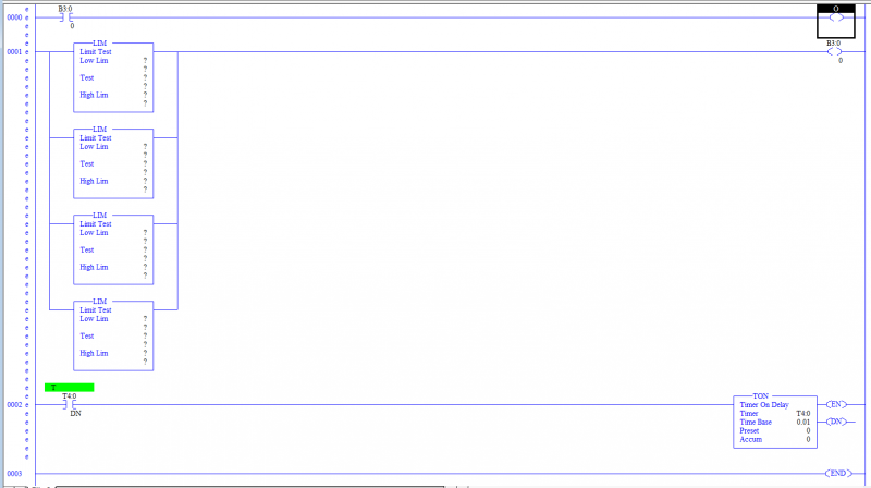
EDIT: Your program does this:
1. When Start bit goes ON, nothing happens for 1.5 seconds, then the Output goes ON.
2. Nothing else happens until the Start Bit B3:0/0 goes OFF, then after 1.5 seconds, the Output goes OFF.
3. That is all it does. I am sure there are simpler ways of going that!
If you told us the nature and purpose of these "pulse trains", then we can come up with some good suggestions.
Here is one way to simplify your program: remove the extra timers that are not doing anything.

Last edited:
Studying the original program, it appears that you might be trying to come up with a way to start up a sequence of equipment, then shut that same equipment down in the reverse sequence. If so, a good easy way is to set up two timers, a TON "START-UP TIMER" and also a TON "SHUT-DOWN TIMER". Then use Start-Up timer LIMs in your start circuits, and for Shut-Down use a Shut-Down Timer TT bit in series with a LEQ for each piece of equipment. That way only 2 timers can start up and shut down any number of motors or devices.
I have examples that I can post, if this is what you are trying to do.
I have examples that I can post, if this is what you are trying to do.
Last edited:
Studying the original program, it appears that you might be trying to come up with a way to start up a sequence of equipment, then shut that same equipment down in the reverse sequence. If so, a good easy way is to set up two timers, a TON "START-UP TIMER" and also a TON "SHUT-DOWN TIMER". Then use Start-Up timer LIMs in your start circuits, and for Shut-Down use a Shut-Down Timer TT bit in series with a LEQ for each piece of equipment. That way only 2 timers can start up and shut down any number of motors or devices.
I have examples that I can post, if this is what you are trying to do.
Thank you guys, Thank you again Lancie! This is a graphical representation of what I'm trying to accomplish. My solution works but too many timers... B3:0/0 is connected to an OSR so B3:0/0 is really always a short pulse.


Thank you guys, Thank you again Lancie! This is a graphical representation of what I'm trying to accomplish. My solution works but too many timers... B3:0/0 is connected to an OSR so B3:0/0 is really always a short pulse.
Here is a better resolution ladder program screenshot showing the OSR added.


Carlisn, you can do this with just two instructions....
Put an SQO in an STI file...
The other instruction is to OTU the SQO control's .EN bit, otherwise it locks up as the SQO never sees more than the first false-to-true rung transition.
Using the STI will also give you better timing accuracy. You may also need an IOM to update the output module if the pulse train has to go to an output.

Here is how I would do it...., and the picture shows the data in the SQO data file
Is O:1.0 an output? I tried replacing it with O:1/0 instead which is the usual format but rslogix doesn't seem to like it... where can I take the output from?
Here is another way using 1 timer. Only the last 2 rungs 4 & 5 are needed. The other rungs are only for setup and monitoring.
Adjust the number of pulses by changing T4:0.PRE, and the pulse width by changing the S:4 Bit up or down from S:4/0 to S:4/15. With this setup, LogixPro produced 4 pulses starting at 1.5 seconds after the Start Pulse.

Adjust the number of pulses by changing T4:0.PRE, and the pulse width by changing the S:4 Bit up or down from S:4/0 to S:4/15. With this setup, LogixPro produced 4 pulses starting at 1.5 seconds after the Start Pulse.
Last edited:
Here is another way using 1 timer. Only the last 2 rungs 4 & 5 are needed. The other rungs are only for setup and monitoring.
Adjust the number of pulses by changing T4:0.PRE, and the pulse width by changing the S:4 Bit up or down from S:4/0 to S:4/15. With this setup, LogixPro produced 4 pulses starting at 1.5 seconds after the Start Pulse.
Ok great. I will try this one. The previous one you posted somehow wasn't working on my setup. I don't have a stop button wired to the plc but now I see is a good idea to have it so I will do that today. I'll let you know how it works later on today. Thanks.
Similar Topics
I would like a sanity check on an application i am working on.
I have a proximity switch counting pulses with a Mark/space ratio of 1:1 on a...
- Replies
- 2
- Views
- 1,875
Hello, I am using pulse train output to a stepper driver to control a stepper motor. It seems to work fine except when I use a Control Stop...
- Replies
- 16
- Views
- 3,316
Hello All
I have a system using the ML 1400 plc. I have an encoder on HSC:1 input 4.
I want to pass this signal out on a FET output to another...
- Replies
- 5
- Views
- 1,959
Dear Expert,
I am doing troubleshooting positioning control in Servo amplifier Mitsubishi MR-J3-A. He get pulse train input from FX1N.
PLC...
- Replies
- 1
- Views
- 1,667
Hi, i already make a program CP1E with pulse train ouput (PLS2) to control stepper vexta. Can i use work online simulator in cx-programmer to see...
- Replies
- 1
- Views
- 1,456