Unity Pro Modbus Communication

atomtm

Member
Join Date
Jun 2014
Location
Germany
Posts
130
Hello everyone!
I am very new to the world of plcs with basic knowledge about their communication capabilities.
I am trying to figure out how the modbus protocol is implemented in Schneider's Unity Pro . To be more specific the I/O Scanning feature .
Is there any guide on how to send a simple bit from a master device to a slave device using simulation software like this : http://www.plcsimulator.org/.
I am sorry for this general question but I don't know where to begin with!

Thank you in advance

http://www.plcsimulator.org/
 
You don't state what product you have as there are multiple platforms and devices that support IOScanner service, and the configuration is different for older vs. new generation modules. So I'm left to guess, and I guess it's a CoPro on a Premium CPU.

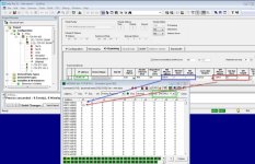
I've used this simulator before for testing and it works. Here is how I have it working now:

ServerSimulator.jpg

I run the simulator on my PC, with IP 192.168.3.10 (in green box in IOScanner config). The simulator is set for ModbusTCP (other green box), and that's all that is really needed on the PC side. Be sure your firewall is disabled or allow TCP port 502, whichever you prefer.

For IOscanner, enter the PC IP address as shown, I choose UnitID 1, but you can choose anything for this test, set your timings - I arbitrarily choose default health timeout and then a RepRate of 250ms. This is really a period, not a rate - time between ModbusTCP queries. Then the registers are called out on both ends - where to get/set data at the PLC side (%MW addresses), and where to set/get on the simulator side, and I pointed to where they end up in the simulator. Notice the (in)famous off-by-one Modbus addressing. Whether this affects you or not depends on the products in use.

Also note that you can't just write a 'bit'. IOScanner service only supports Modbus function codes 3, 16, and 23, which are for the Holding Registers memory area. The simulator supports bits, but you would have to use an explicit message block of some sort (depends on platform, maybe MBP_MSTR, Read_var, what have you) and you could then use a Modbus function code for bit operations. This is significantly harder than using IOScanner, but in some specific cases, wants/needs to be done. Frequently, bits can be aggregated into words and passed with the word operation functions, and bits can be extracted from the words on other end so often times it's not an issue.

I glossed over - actually ignored - many of the beginning steps of this. Configuring the network parameters of your Ethernet module; configuring the network parameters of the test PC, etc. Let us know where you are having difficulty and we can provide more information.
 
Many thanks for your reply ! Really appreciate it!
I use Unity Pro XLS with an TSX P57 2634M cpu (+ ETY port module).
To get things clear, how exactly do you use %MW and %M in general for modbus communication ? Are there any standards for the addresses you access with these memory words ? For example I noticed you point %MW0 to 40001-40010 region and %MW1 to 40011-40020.Is there any rule about the modbus regions you access using different %MW?
Another question at this point is who polls the data , the simulator or the master with the configuration you suggest , or is it bidirectional?
As I told you I am very new so please forgive my ignorance!
Once again thank you very much for your effort!
 
Communication is considered unidirectional in my view: there is a logical 'master' and a logical 'slave', or in network terminology

master = client
slave = server

The client initiates a TCP network connection to the server, and then issues Modbus requests or queries. Good reference is the Modbus spec, which is an easy read in a couple of hours. Get the protocol and the Modbus TCP/IP documents. If you have ever used Wireshark, it might be useful to run at the same time as you are reading the document/testing the system as you can watch the protocol in action.

In your test, the client is IOScanner and the server is the simulator package. The client can read and write registers, but it controls what happens. All the server will do is execute the operation that it is instructed to do - read or write. The slave does not issue Modbus queries on this connection. It could act as a client and connect back to the PLC, but I am not sure this particular simulator has the capability. The PLC can act as both client and server, at the same time.

The ETY is a Premium module so configuration should be consistent with the screenshot posted. Since IOScanner only deals with %MW memory, or 16-bit words, you would have to manipulate any bits (%M) in code and aggregate them into words. The %M and %MW are different memory areas that you can use to store information. The Unity helpfile, in the early chapters, has a good section on describing the different memory types.

These memory areas in the PLC map directly to Modbus memory areas. The specification will detail these, but they are very simple because there are only a few of them, and they are flat. The Holding Registers area is denoted by a 40000 series address, so starting at 1,

Register 1: 40001
Register 2: 40002
....
Register n: 4nnnn
etc.

There are other memory areas, such as for bits. These would start with 0xxxxx, and 1xxxxx, and there is an input register area for 16bit words that has a 3xxxxx series address. The mapping for Premium appears to be, for what we need:

%MW0 -> 40001
%MW2 -> 40002
...
%MW10 -> 40010
....

In my example, IOScanner is setup to READ (see columns and settings in blue box from screenshot):

RD Master Object: %MW0
RD Ref Slave: 0
RD Length: 1

This means start at register 0 in the slave (Ref slave), read one register (Length), and place in %MW0. So when running, if you change the simulator register 0 - notice the change in nomenclature - sorry about that, but it's not my design - it will show up in the PLC in %MW0. If you wanted to read, say, 20 registers, change the length to 20 and the read will start at the first register in the simulator (40001) and read the next 20 registers, and store them starting at register %MW0 in the PLC, out through %MW19.

For the WRITES, it is the same concept of offset/length:

WR Master Object: %MW1
WR Ref Slave: 10
WR Length: 1

So whatever value I put in %MW1 will be written to slave register 10, which is 40011 in the simulator. In fact, in an animation table in UnityPro, I put in the value 123 into %MW1 and it shows, as it should, in this register in the simulator.

IOScanner supports function codes:

fc3: Read Holding Registers
fc16: Write Multiple Registers
fc23: Read/Write Holding Registers

So it only operates on the 4xxxx series Modbus addresses. The other memory areas are not available to you with this particular tool.

The tool will choose which function code(s) to use depending on what you enter for configuration, and what the server supports. If you only enter READ configuration, then only function code 3 will be used. If you only enter WRITE configuration, then only function code 16 will be used. If you enter both READ and WRITE configuration, then the tool will attempt to use fc23. Upon error, it will fallback to a separate WRITE with fc16, then an immediate READ with fc3.
 
Hello robertkjonesjr ,
I am trying to recreate your example , based on the info/attachement you provided but I got into some errors.
First of all I configured the ETY module with an IP configuration same as yours :
IP : 192.168.3.101
Subnetwork: 255.255.255.0
Default Gateway : 0.0.0.0

I didn't know about the Ethernet Configuration so I left it to default Ethernet II.

The IO Scanning tab is identical to yours .
I then created an Animation Table with %MW0 as INT .
I disabled the WIndows Firewall (Windows XP on VMware 9) opened the simulator, configured it like you posted and set the PLC to simulation mode (which gives 127.0.0.1).
I also changed my Ethernet adapter to 192.168.3.10 with subnet 255.255.255.0.

The problem is that when I try to connect I get the following error : "This isn't a valid PLC address , or PLC is busy , or media is off".
Are there any other configuration I should do to get a connection between Unity and the Simulator?
 
Last edited:
I might be wrong, but I think that IOscanning doesn't actually work in the simulator. Check the help file.

You'll need real hardware to test this.

You can of course simulate the modbus slave that the PLC is communicating with using software on your PC.

And to be able to connect to the unity simulator you need to change to simulation mode. Then check the communications parameters, from memory there is a little tick indicating that simulation is selected.
 
No IOScanning on the simulator, sorry, as mentioned by Saffa. You'll need real hardware. The simulator will act as a server, but that's not what you want: you want a client, and can't get that with UnityPro simulation. Even then, except for a smoke test to see if it might work, I would never really test communications with the simulator, even if possible. They are completely different stacks, and performance will be very different.
 
Seems that I am able to connect to the PLC in simulation mode ,transfer Project to PLC and Run it but there seems to be no communication between Unity and the simulation software .
I have created an animation table with %MW0 , %MW1 and (on the Simulation software side ) I am triggering register 40001 (e.g. I set it to 123 ) without any change on %MW0 . Similarly when I modify the value on %MW1 , there is no change on 40011 register.
Am I missing any other configuration?
I could make a new post with all the steps I did to configure Unity Pro and my computer if that helps.

Thank you for your interest
 
So to clarify this , is there any way to test Modbus communication without any real hardware using Unity Pro ?
As I mentioned before I am still learning and the goal is not to reproduce any real-world application but just experiment with the protocol.

Another question might be how single bits are remotely triggered in a ladder section for example (I have seen %M0 without the read_var /write_var or any other message block - in applications to be triggered remotely but can't find out how Unity differentiates this from internal memory bit and recognizes it as a modbus message, so I thought this would be done with IO Scanning) and if there is anyway on testing this procedure without any hardware.

I still have lots of questions on the subject but don't want to spam the forum , so I might keep reading the manual and post a new thread in the future.

If you still could answer me the above questions I would be very grateful.

Thank you
 
So to clarify this , is there any way to test Modbus communication without any real hardware using Unity Pro?

As a client, no. You need hardware. For learning, there are free Modbus clients out there, too - I guess they don't help with learning Schneider products, but if it's only Modbus you are interested in, then there are solutions. Check Codesys - pretty sure they will allow you to run logic on a PC and have client communications, if that's a path you want to take.

Conversely, for testing SCADA or HMI, the UnityPro simulator works OK because it can act as a server, and you can point your SCADA or HMI software to the UnityPro simulator and get things to work for a test. Don't evaluate performance if you do this, but it's good first check to be sure things are working.
 

Similar Topics

Hello i want to implement a Read_var / Write_var functions to communicate with a modbus tcp device at the moment i use the unity simulator at the...
Replies
4
Views
1,919
Does anyone have a good doc that explains the addressing for modbus with unity. I am having issues setting up the addressing when trying to...
Replies
7
Views
3,977
Hello, P.S: I am new to this Forum, please excuse me if i ma writing in the wrong section or if i used something that isn't accepted within this...
Replies
11
Views
4,355
I have a confusion regarding modbus addressing that it looks like in unity PLC we can only access 1x (%Mx) and 4x (%MWx) registers and we have to...
Replies
3
Views
4,738
OK Gang, I'm setting up a M340 system using Wonderware as the HMI and I really want my DASMB server to match the addressing in the PLC and not be...
Replies
0
Views
2,198
Back
Top Bottom