PLC5 Scaling Question

jrowe4

Member
Join Date
Jul 2012
Location
palos park
Posts
16
I have a question regarding PID scaling on a PLC5. I have a cascade PID loop setup where a dryer's outlet air temperature controls an inlet air temperature.

My outlet air temperature PV range is scaled from 0-200 C. and my inlet air temperature PV range is scaled from 0-400 C. However, the issue is that my burner can not achieve a range of 400 C. Simply, I want to adjust the scaling.

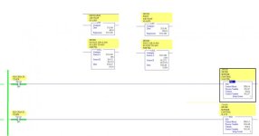
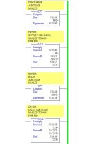
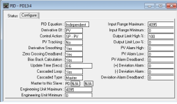
I am achieving my current temperature ranges by scaling type J thermocouple data into 0-4095 for use by the PID blocks. For example, I am scaling the outlet air by 20.475 and the inlet air by 10.2375 to put both into the range 0-4095 (shown in the scaling.jpg attachment).

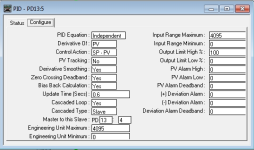
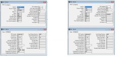
I am using type PD PID blocks set up for cascade mode. I am also using 0-4095 respectively in the engineering unit min and max parameters (shown in the master/slave.jpg attachement).

I want to change the outlet air scaling to 0-150 C. and the inlet air scaling to 0-250C. Would I just have to pick new scaling factors (the 20.475 and 10.2375) to get my new ranges or do I need to mess around with the engineering unit min and max parameters?

It would be nice to work with EU instead of raw data, but I feel I would get the same results either way. I am not sure if my way of thinking is correct, so I turn to the experts on this stuff. Thanks for any help you can offer, I appreciate it!
scaling.jpg master2.png slave2.png
 
It would be better if you can post the whole program , its .RSP file ( zip it first).

Where does F15:48 and F15:49 come from? Is there a thermocouple card or?

It appears that F15:48 and F15:49 are already scaled to engineering units.
 
Last edited:
Sorry, I can not post the entire .RSP file due to IP. However, I have attached two images with all the revalent info regarding this control loop.

F15:48 & F15:49 are comming from a 1771-IXE selected to read celcius for type-J thermocouples. These floats hold real world temperature values. So if F15:48 reads 70, it is measuring 70 deg C out in the field.

F15:48 gets scaled by 20.475 to put into the range 0 - 200 C (200*20.475 = 4095). F15:49 gets scaled by 10.2375 to put into the range 0-400 C (400*10.2375 = 4095). The scaled floats get moved into integers and are used as the PV's for a cascaded PID loop setupt. Basically, my PID loops are using raw values for control.

My issue is that my burner is cycling between on/off and is causing problems with flame efficiency. The loop is set up that the dryer outlet air (master) sends a SP for what the inlet air (slave) should be. The master loop is writing SP's to the slave that I can never achieve. I am thinking this is because the scaling is incorrect (my burner over the past year has never produced an inlet air temperature over 220 C). So thats why I want to change the scaling.

I'm not sure if I need to just adjust the scaling factors or if I need to use the engineering unit min/max fields found in the PID blocks. I actualy adjusted the scaling factors from 20.475 to 27.3 and 10.2375 to 16.38 to get my new ranges (0-150 C for outlet and 0-250 C for inlet). However the whole system went crazy so I changed them back. Maybe because of built up error in the PID block and I need to make the scaling switch on a cold startup, not sure. I am really a noob when it comes to PID.

Anyway, I hope I cleared this up a little bit better. Again thanks for the help, I really do appreciate it!

scaling info.jpg pid info.jpg
 
You can do that rescaling but you will also have to rescale your setpoints.

A 1771-IXE does not put its raw data into a floating point register (it puts it into an integer N??:??? data type) so somewhere there is a mov or data manipulating instruction. Hopefully there is also some limits check so the value does not exceed the limits of your engineering unit scaling. The raw data from your thermocouple card set for type "J" is -210 to 1200 C. After scaling to 0-4095 (using your engineering unit values) that value can go out of that range. The PID instruction for a PLC5 does not like values out of range.

I would take the raw data from the card its integer data type register scale that to (-210 to 1200) 0-4095. Use that as your PID's PV input.
Then use the PID's "Engineering Unit" min/max to scale the PV input (0-4095) to -210 to 1200. This will required you to enter the setpoint in engineering units.
 
Last edited:

Similar Topics

Hello everyone, I am migrating a PLC5 program controlling a crane to a siemens s7-1500 PLC, but since i have no experience programming PLC5 I have...
Replies
8
Views
2,966
I have a question regarding the Engineering Unit Min / Max and the Input Range Min / Max parameters on a PID block in a PLC5. Typically I've seen...
Replies
0
Views
2,270
I have a 4-20ma input to a 1794-IE8 Flex I/O module. The Flex I/O is talking to a PLC5/40. What is the correct value to use when scaling the raw...
Replies
2
Views
4,525
Hello again. I have a question about PID controls. When looking on at a PID control block in a PLC 5, I can see where the input range is scaled...
Replies
2
Views
43,832
Back
Top Bottom