Speed conditioner problem.

Elcan

Lifetime Supporting Member
Join Date
Apr 2008
Location
NC
Posts
935
Hi all,
We are trying to start up a machine that is operated by 2 motors. There are proximity switches to read speed from each of the moving parts associated with those motors. The signals from those proximity switches are delivered using 3 wires to a signal conditioner (one set of switches and a conditioner per motor). The signal conditioners are Pepperl+Fuchs KFD2-UFC-1.D .
The motors are controlled by VFDs.
The problem we noticed is that the speed read by the conditioners is erratic. In general it's correct until around 10 Hz, then, when we speed the VFD up, is goes up to around double it should be. Sometimes if we go up very slowly, like 1 Hz per minute the speed conditioner seems to tolerate the increase and reads well, but sometimes is doesn't.
We also noticed that the speed signal from the smaller motor (15 hp) is more likely to read well than the one from the big motor (75 hp).
We even ran a cable outside the conduit to rule out a wiring problem like wrong wire or electrical interference.

Has anyone experienced something like this in the past?

Thank you very much in advance!
 
Does the switching frequency and pulse duration of the sensor match the specification of the frequency convertor?

Nick
I really don't know. The proximity switches were provided by the machine manufacturer.
I've worked with similar machines and the same conditioners in the past, and hadn't had similar problems.
 
Do you guys think that any of these things can be affecting the speed reading the way I told you?:
* Signal shield grounding
* VFD grounding
* 24 VDC power source grounding
* Signal interference in the conduit
 
The most likely source of noise is poor grounding of the screen on the motor cable. This should be maintained continuously between the motor and the drive with a the full 360 degree of screen grounded at both ends but not anywhere inbetween i.e. not at the entry point of the panel. Surface area is important in this instance as skin effect applies at higher frequencies. The switching frequency of the drive is probably 4Khz which isn't that fast but you must considder the rise time of the voltage which implies a much higher frequency.

Do you have a noise problem? Put a scope on the signal to see a) noise b) how clean is your pulse train.

Nick
 
i doubt it is the converter, as this sees pulses and converts it to current. I would check the sensor (its connections and if the sensor is correctly placed, pull it back a little i would say. If the sensor is slow with falling it can not cope higher speeds. (clean the head , when iron is present you get slow response
when using calculation the speed is limited to 550 Hz, but that is 30000rpm when using one puls /rotation.
 
We removed the converter from the panel, ran a cable outside the conduit, placed the converter close to the junction box where the proximity sensors are located, and fed the converter from an independent power source. The issues were still there.
Now we know the problem is not something in the panel interfering with the converter.
A new sets of proximity sensors are being sent to the plant. We'll see if the problem is the sensors.
 
This machine sounds like it must be decanter.

You refer to the speed reading being erratic...

Is it 'jumping around' or is the reading steady but just wrong?

Is the reading you refer to what you're see on the frequency convertor display or on your monitored signal i.e. HMI.
Are the frequency convertor display and your output signal consistent with each other?

It may be worth while going thru the setup of the frequency convertor and checking it all matches the application.

And as shooter mentioned, check the positioning of the sensors.

Or I'd wonder if the sensors are either incorrect for the application or failing.

I don't think it is noise.
 
Last edited:
Other ways for trouble-shooting.

(If the conditioner/converter setting is the best and cable connection/polarity correct/good)

A.) follow as member suggestion use oscilloscope if possible.

1.) use pulse generator or PWM inject at the proximity location (remove the PX- use the cable) start with 1 Hz step by step until max.

if possible the voltage same the proximity. Run the VFD.

Read the value.

Since this trial test and speed reference VFD in manual/local mode.

2.) The moving part to part pulse duration time? Check the pulse wave (oscilloscope)
Or what happen if part is missing?
3.) check the gap PX with object.
4.) dimension/thickness area of object to sense.
 
Guy,
Thank you very much for all your comments.
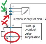
At the end, it was a wiring problem. We misunderstood the schematics in the converter manual. We swapped a couple of wires and now we are reading correctly.
I'm attaching a snapshot showing the reason of our confusion. We found out that the convention in the schematics is to place the "+" symbol above its corresponding wire, and the "-" symbol below its corresponding wire. We had though the "-" terminal was #3 and it was #2 instead. Terminal #14 is a clear example of this convention.

Speed_Sensor_Input.jpg
 
Last edited:

Similar Topics

Does anyone know what the data transfer rate for this series of CompactLogix PLC's? 1769-L24ER-QB1B to be exact. Cheers.
Replies
1
Views
88
Hello, I am trying to setup on plc so If I enter 60 jph (job per hour) it will send the vfd hertz based on what jph is entered by...
Replies
2
Views
152
Sigh, DeviceNet noob... I have a 1756-L55, with a DeviceNet module, and 10 PF700 all commanded with DeviceNet. One of the PF700's blew up...
Replies
3
Views
128
Do i have to use interrupt subroutine, or immediate read high speed input, for Unitronics Samba plc or reading only the correponding register in...
Replies
2
Views
121
Hi all, I'm having trouble solving a problem I've been working on for several months, and thought you might like a stab at it. The machine runs...
Replies
22
Views
925
Back
Top Bottom