upgrading heating control challenge

LessThanThree

Member
Join Date
Jul 2014
Location
Wisconsin
Posts
32
I am upgrading a directlogic system to Point IO on a controllogic platform and have ran into an interesting challenge.

The temperature control is done by by sending a +24vdc signal to the T1 terminal in a Honeywell Modutrol IV motor M9484F1023. The T2 is wired to the channel 1 + side of the 4-20mA analog output module. The negative side of the channel is connected to the 24vdc common. Please see attached schematic if this is not clear.

I have tried wiring the new module to feed a 4-20mA, 24vdc signal directly to the modulating motor but the equipment will not move. When I wire with the same setup as the exising parts my module faults with an error that a signal less than 1mA being generated.

I have attached the relevant schematics. I apologies for the picture quality. They are from the only known version which was a fax over a decade ago.

I am trying to understand why it is wired the way it is and how we can make it work with the new equipment.

Any suggestions for strategies or equipment would be greatly appreciated.


Link to the Honeywell motor:
https://customer.honeywell.com/en-US/pages/product.aspx?cat=HonECC Catalog&pid=M9484F1023/U

Link to existing module:
http://www.automationdirect.com/static/manuals/d2anlg/d2anlg.html

Link to replacement module:
http://literature.rockwellautomation.com/idc/groups/literature/documents/in/1734-in034_-en-p.pdf
 
heating control

you have it configured right and comms are established? i attached screenshots from the manual

screenshot.46.png screenshot.45.png
 
With Automation Direct, you need to provide loop power as shown on your existing schematic.
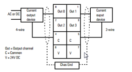
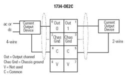
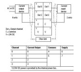
With AB, loop power for Channel zero is on pins 4 and 6. Channels 1-3 are on pins 5 and 7. It's not clear how the 24DC supply is connected.

1) Connect Honeywell controllers:
Wire 1200 to 0 (Out 0)
Wire 1210 to 4 (C)
Wire 1220 to 1 (Out 1)
Wire 1230 to 5(C)

2) Verify loop power.
I've never used this AB product. It's not clear to me how the loop gets powered. Are pins 6&7 connected to +24 DC, 4&6 to 24 DC return, or do you need to make connections? A clue in this link.
 
The supply voltage to the modulating motor you have provided a link to is 24VAC.

That supply voltage is AC, it is constant, and is not varied to control modulator motor position.

The modulating motor you provided (90 series) is not controlled via 4-20mA, it is controlled by external potentiometer.


The motor position is controlled by a 135 ohm potentiometer, or a series 90 controller.

Two potentiometers, one in the controller and one in the
motor, along with the motor resistor network, form a
bridge circuit. As long as the value of the controlled
medium remains at the setpoint, the circuit remains
balanced and the motor does not run.

When the controlled medium value changes, the
controller potentiometer wiper moves, unbalancing the
bridge circuit.

The imbalance is amplified and energizes switching to
drive the motor in the direction necessary to correct the
controlled medium change.

As the motor shaft rotates, it turns the feedback
potentiometer, rebalancing the bridge circuit, stopping
the motor.
 
OP posted link for 4 channel - ...OE4C diagram applies. I'm certain the problem is related to powering the loop. OP hasn't posted a reply yet.
 
OP posted link for 4 channel - ...OE4C diagram applies.
Yes, that is fine for a modulating motor with a 4-20 mA input. Unfortunately, the Honeywell Modutrol IV 24 VAC motor M9484F1023 does not accept a 4-20 mA input signal. It should be replaced by one of the motors in the link that Milldrone listed in Post #5. Either the motor or the control method will have to be changed.
 
Last edited:
He said he is replacing an existing control system from AD to AB. The attached schematic in post #1 shows 4-20 mA control. I'm basing my comments on that.
I assume he posted the wrong datasheet for the Honeywell unit. We can't know until he responds.
 
The attached schematic in post #1 shows 4-20 mA control.
Are you sure about that? All I see is DC control originating from a 24 VDC source, which could be something other than a 4-20 mA signal (maybe a 0-10 volt or -10 to +10 volt signal).
 
Last edited:
The +24 signal you see is Loop Power. The AD link covers the full range of analog products, but the schematic shows a 2-channel device. I assume it's a F2-02DA-1.

If you ignore the issue with the Honeywell unit, all the rest makes sense. The +24 loop power is wired externally with AD. It's internal on the lower terminals with the AB unit.

It looks like a working system. He pulled an AD PLC, and replaced it with an AB. Has a problem figuring out the analog wiring - specifically loop power.

Why are we telling him other hardware is wrong, and trying to replace the Honeywell? This a control system for roasting coffee beans. There's other hardware we don't see. There is probably a controller driving the Honeywell, with a 4-20 mA input.
 
Why are we telling him other hardware is wrong, and trying to replace the Honeywell?
Simply because the Honeywell that he quoted does not accept a 4-20 mA signal, but accepts a voltage signal (potentiometer or Open/Close switch).
 
The original poster should consider that regardless of the honeywell actuator type;

There are NO 4-20mA DC current loop connections to 24VAC terminals T1 and T2, as he stated in
post #1, even if he had shown or referenced a compatible model with current input;

Honeywell M7274Q1009/U

T1 and T2 are for 24VAC modulator motor drive power and internal circuits, seperate + and -
terminals are provided for mA signal.


Perhaps he misspoke about the connections, or maybe 24VAC is being "infused" by improper
connection with the 24VDC of the alalog output card, and thus, analog output card error?


The problem is he can't send "a +24vdc signal to the T1 terminal in a Honeywell Modutrol
IV motor M9484F1023" and connect the T2 terminal to "the channel 1 + side of the 4-20mA
analog output module", and expect it to work.
 
...Perhaps he misspoke about the connections...

The problem is he can't send "a +24vdc signal to the T1 terminal in a Honeywell Modutrol IV motor M9484F1023" and connect the T2 terminal to "the channel 1 + side of the 4-20mA analog output module", and expect it to work.
Yes and yes. But, read the next sentence: "Please see attached schematic if this is not clear ".

I don't disagree that the Honeywell is not 4-20 mA. The magic box that converts 4-20 mA into the pot signal isn't shown. It must be there, or we can throw out the schematic too, because AD doesn't make a module that will directly connect to the Honeywell.

This was a working system, right? On page 2 of the schematic, the wiring for an AD analog output module is clear. We can ignore his description of wiring. Ditto for the Honeywell. We don't need it. The schematic tells us all we need.
The question is simple. How to wire the AB to work like the AD did?

Based on his description of wiring, I assume he's not an expert on 4-20 mA.
He didn't recognize that the +24 is the loop power. So, I told him how to wire it point by point.

Then we reach my shortcoming. I've never used the AB module. Can't make sense of the documentation regarding loop power. Terminals 4&6 are for the first channel, and 5&7 for the other three. Is it already powered, or do you need to connect 24DC to them? Do we need to jumper 4-5 and 6-7 to get power to the other three channels?
 
Sorry for the late reply everyone. IT took away our ability to post on internet forums so I am replying from home.

Keith, your wiring suggestion was correct. I can control the valve completely.

JRB, thank you for the explanation. It is much less of a mystery.
 

Similar Topics

Hi, I am upgrading a Wonderware SCADA form version 9.5 to version 23. I am able to migrate all the graphic, but when to activate the runtime this...
Replies
8
Views
402
We are in the process of upgrading a controls system. The existing system is a SLC500 with some IO cards and a 1747-SDN module communicating to a...
Replies
5
Views
538
I am looking to upgrade some of our old Servo Drives to the newer kinetix 5700 style. currently we have 4 1394 axis that are all driven by 5kw...
Replies
1
Views
876
Hello, We are currently running a bunch of g310's connected to their SLC5 PLCs through ethernet. I've attempted to upgrade the program from 2.0...
Replies
1
Views
1,119
Hello everyone, My company has an old line for building DC motors. Many machines are from the early 90's and some requests for safety...
Replies
2
Views
1,154
Back
Top Bottom