Need Help With Input Card on GE Fanuc Series 90-30

g_4key

Member
Join Date
Aug 2014
Location
SC
Posts
42
Hey Everyone,
I'm in a bind here at my job we have a GE FANUC Series 90-30 PLC with a embedded CPU in the base plate with 5 I/O Slots our CPU is the model 311 part/model (IC693CPU311) that contains a power supply IC693PER321 120V AC input and DC output we have the following modules/ cards a horner electric HE693ASC224 Ee Prom Basic Module, one analog input, one discrete input, one discrete output and one analog output. But our discrete inputs are not registering in the input tables our switch to change between a manual and auto mode will not show up. The field wiring was checked and the switch which is working perfect. No faults exist in the I/O or PLC, I Cant force it or toggle for some reason this model is unable to do that. But if i'm wrong let me know. One odd thing is that i switched the card out a 16 pt DC Input IC693MDL645 (http://www.*********.com/pdfs/ic693mdl645.pdf) everything went back to normal powered it down next-day came back in powered it on and same thing inputs aren't showing again tried swapping old card back in and no result. Any ideas on what to check? One side not is that I did make sure that the I/O cards matched what was in the Rack configuration in Logic Master 90. Let me know if you need more info. or file will be happy to supply it any help would be extremely needed since im totally lost confused and green to industrial maintenance other than what i learned in tech school which sadly has probably been forgotten
 
Last edited:
The symptoms you describe are consistent with the PLC losing its configuration file when powered down. Is the LED labeled "BAT" on the power supply lit? If it is, you need to replace the battery. Without a battery you will need to download the program and hardware configuration file to the PLC every time you power it up.
 
Here are a few things to check.
1. Make sure the PLC is actually running. If it is the LED labeled "RUN" on the power supply module will be lit. Normal operation has the "PWR", "OK" and "RUN" LEDs all lit and the "BAT" LED off.
2. Make sure the LED on the discrete input module corresponding to the switch turns on and off when you make and break the switch.
3. Check the I/O fault tables using Logicmaster software. If the PLC loses contact with the discrete input module, you should see a "Loss of I/O module" entry in the fault table. If it re-establishes contact with the module, you should see a "Add'n of I/O module" entry.
4. When you online with the programming part of Logicmaster software, you should see a message in the lower right hand corner of the screen that says "Logic Equal". If it says "Logic not Equal", you won't see the state of the input point change when you actuate the switch.
5. When you go online with the configuration part of Logicmaster software the message in the lower right hand corner will be "Config Equal" or "Config not Equal". To get the message to say "Config Equal" you will need to make sure the actual population of modules matches the Logicmaster list.
 
Good morning every one and thank you Steve for the suggestions! Here is a brief report RUN led is on, PWR led is on, OK led is on and BATT led is not on, there is no response for the input led on the card for the corresponding input i have verified the input is working and the field wiring as well, I/O Fault tables did read a Loss of of I/O Module and Add'n of I/o Module. Faults were cleared and the issue still persists. Good news is Logic Master 90 software shows Logic Equal and Config Equal. One thing on a side note is that my direct supervisor attempted to show me how to load a program file from the programming pc into the GE Fanuc 90-30 using the Logic Master software i cant remember what exactly happened, but I'm wondering if maybe we "goofed" it up at that point?
 
there is no response for the input led on the card for the corresponding input i have verified the input is working and the field wiring as well
The LEDs on the MDL645 are on the field side of the circuit. The signal from the switch is not getting to the input module. Check the wiring all the way from the switch to the module. Make sure the removable terminal strip on the module is properly seated. There is a tab on the bottom of the terminal strip that mates with a slot on the module. It is possible to install the terminal strip without putting the tab in the slot. When you do that, it may appear that the terminal is properly mounted, but all of the terminals may not be making contact with the circuit board.
 
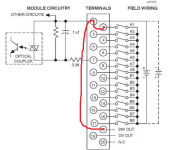
Now I did remove the strip and re-inserted it back into the card and the same result no inputs are displaying. I also checked the strip itself and made sure it was for that model and it was, I'am getting 24v DC at the 24V out terminal 18 and either 19 0v out or NC terminal 20. Now is terminal 20 the Common terminal or is that terminal 1? Could one of the terminals be shorted preventing the inputs to show up?
 
On the MDL645, terminal 1 is the common terminal. NC on terminal 20 means "No Connection". If you are using sourcing sensors (sensors that switch on the positive side of the DC line), you connect the DC- wire to terminal 1. If you are using sinking sensors you connect DC+ to terminal 1.
 
On the MDL645, terminal 1 is the common terminal. NC on terminal 20 means "No Connection". If you are using sourcing sensors (sensors that switch on the positive side of the DC line), you connect the DC- wire to terminal 1. If you are using sinking sensors you connect DC+ to terminal 1.
So as this module has only one "Common", you can use one or the other type of sensor either PNP or NPN.
 
Could I eliminate the card or inputs as a source of the problem if i were to take a jumper from 24v out into the common or a input terminal?
 
http://www.*********.com/pdfs/ic693mdl645.pdf

yeah its an input card this model to be exact, i believe i used the same Figure for the input card/module.
 
Last edited:

Similar Topics

Hi, I am pretty good with Rockwell gear but I am fairly green when it comes to Siemens and I am having difficulty finding where an analog ASi...
Replies
11
Views
3,970
Hi, I have a Micrologix 1400 with a 1762-IQ16 discrete input module, wired for sinking inputs (common to DC-) I have an instrument with the...
Replies
5
Views
12,717
hello... i'm trying to take an analog value from transmitter.. i'm using OMRON CS1G-CPU45, and the analog module is CS1W-AD16, the analog value is...
Replies
1
Views
1,444
I've got a AB PICO 1760-L18AWA, it accepts 120V input. I've got a circuit going thru a 120V solid state relay (SSR)that is activated by Thermo...
Replies
7
Views
2,854
I'm fairly new to Rockwell software, I've had some basic training in the past but nothing too advanced. My company and I use Reliable products for...
Replies
11
Views
318
Back
Top Bottom