First Panel - First CAD work - Criticisms and comments welcome (pictures)

bimmersix

Member
Join Date
Jul 2014
Location
PHX, AZ
Posts
38
Hey everyone.

Within the next two weeks I will (hopefully) have built my first panel.

I had the odd fortune/misfortune (time will tell) of telling my boss about a type of equipment used in our industry that could be quite profitable to us if we could obtain one and refurbish it. Having used/diagnosed/serviced/fixed dozens of examples of poor design, I opened my big mouth that I'm sure there is a better way, and I'm sure that I could figure it out.

So he gave me a budget, enough for components but not enough to hire an integrator, and suddenly I realized how much I don't know...

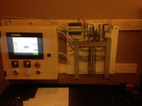
Now I've written and tested my first PLC program, programmed an HMI interface and can successfully remotely operate my test station. Started my first CAD work and I'll finishing the wiring diagrams soon (before building the real thing). The HMI/temp controller panel is way more cramped than it will be - that was just a first attempt at the cutouts for a trial run before cutting into anything expensive. (Also, the buttons/e-stops are old - just for testing).

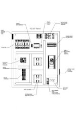
Attached are a PDF of the basic panel design and a picture of the test station which is scaled to be the same as the PLC and I/O terminals in the real thing. I don't have wire labels yet (in transit) which I know I need. I plan to label both sides of the terminal blocks. Will also use thin-finger duct - should be neater.

Comments/criticisms welcome. I would prefer that it not LOOK like a first panel, if I can avoid it... And many of you have already helped with advice and pointing me toward helpful articles.
teststation (Medium).jpg Panel.jpg
 
Not bad for a first time. One suggestion I have is to add device tag names to the panel layout drawing along with the descriptions you have supplied. Since tag names often contain a line reference to either you electrical drawing or a P&ID drawing it helps to locate the component on the other prints. For example, the power supply might be tagged PS140, the user knows he can locate the power supply on line 140 of the electrical drawings, with the first number also designating the page number in multi-page drawing sets.
 
Last edited:
Not bad for a first time. One suggestion I have is to add device tag names to the panel layout drawing along with the descriptions you have supplied. Since tag names often contain a line reference to either you electrical drawing or a P&ID drawing it helps to locate the component on the other prints. For example, the power supply might be tagged PS140, the user knows he can locate the power supply on line 140 of the electrical drawings, with the first number also designating the page number in multi-page drawing sets.

Great - thanks - I will do that.

I assume I should have matching nameplates made for components in the panel? If so, do you have anywhere that you recommend sending off for tags to be made? I don't work for a shop so my limited supplies don't include engraving or etching equipment.
 
We use a local sign making shop that happens to also have the engraving equipment. They use white with black lettering GravoPly stock to make the tags.
 
Looking at the (tiny) layout image I think you might not have separated the AC and DC circuits as well as you could. If I'm reading it right you've got some AC distribution to the left of the DC PSU and DC distribution to the right of it. That'll have AC and DC conductors running alongside each other in the same wire duct.

Also am I correct in thinking you've got a VFD in that panel too? That's a noise generator I'd rather not have in the same panel with a plc and other DC controls.

Maybe consider putting the DC circuits in the HMI panel and using a separate panel for your AC power controls.

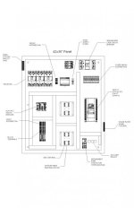
I didn't realize how small that was until you mentioned... I tried to attach a PDF but it was about 50K too big. I guess I resized kind of small... OK - slightly bigger attached.

So the AC will actually all run in the wireway to the left of the VFD. It will be in the wireway above the PLC but no control wires will share duct with AC with the exception of 24VDC to the contactor and aux relays in the bottom right. The AC exits the bottom of the panel.

I don't have the option, on this retrofit, for a second panel. Do you anticipate issues with the VFD? My analogs will be shielded. The VFD will have DC control wire and RS-485 comms that will have to cross the AC duct at a right angle... I couldn't figure out a way around that, using this single panel, but I'm certainly open to suggestion. Perhaps shielded VFD output cable to the motor?

fullpanel.jpg
 
Perhaps shielded VFD output cable to the motor?
This is always a good idea to use shielded cable for load from a VFD to a motor.


Also for your Component tags, most sign or trophey shops can engrave these for you.

You can go online to "Seattle Engraving" and they have an online program where you can design and size your tags to see what they will look like, using different tag and font colors.
If there is no one local where you are you can order directly from Seattle Engraving and have them mail you the finished product.

Keep up the good work, looks like you are off to a nice start.

BCS
 
Unsure what the requirements are in the US in regards to component tags, but I have found that Dymo labels work very well. We use that white-black-core plastic for tag numbers, and often use Dymo tags for trip settings.
 
I think it will help to lay out all the components, wire ducts included, on the backplane and organize them before drilling your first hole. Think about things like how easily the wiring will bend (or not) to make connections to devices and terminal strips, etc. Also, how accessible things near the edges might be after the backplane is installed in the panel.

On the subject of holes, I seem to remember that NFPA wants all component mounting holes to be threaded, no sheet metal screws.

For labeling, include device labels on the backplane itself - that way if later say, a contactor is replaced, the device name won't get lost or have to be reprinted. The Lamacoid type labels are excellent and long lasting but not cheap.

Thanks - I have the CAD drawing scaled so I will print it out and lay out the components as suggested to check the wire bends. That is one thing I'm unsure about. I assume MTW is probably the best to use for flexibility, and I plan to get conductor sleeves for the lug connections since MTW is high strand count. Does that sound like a reasonable plan?

I just (as in about 15 minutes ago) received a set of those Greenlee drill/tap/counterbore bit sets for tapping the backplane. I didn't know NFPA required that though, great info.

Lamacoid type it is, then. I'd like this to have a 10-year service life with possible replacement of the VFD. Thanks all.
 
and I plan to get conductor sleeves for the lug connections since MTW is high strand count. Does that sound like a reasonable plan?

The sleeves are nice. Not so much at this stage because you'll have lots of light and room to work but, they really come into their own when one has to get into the wiring in the field. Panels can be awkwardly located and don't always enjoy the best lighting conditions. Sleeves would also eliminate the possibility of 'whiskers', those little loose strands of wire which don't make it into the connection and can short against other conductive parts.
 
The first time I worked with the sleeves, the lead electrician gave me a couple of bags and I thought 'these are pretty nice'. I REALLY had to tighten the screw terminals on them though, since the wires still pulled out easily. Later, when examining the system for loose wires, he held up three wires and said 'hey, did you not use the crimper?' to which I replied 'what crimper?'. I said if you wanted them crimped you should have asked if I had one or just handed me one ...
They really need to be crimped!
 
On the subject of holes, I seem to remember that NFPA wants all component mounting holes to be threaded, no sheet metal screws.


bimmersix,

In the panel building how-to thread that I linked in one of your previous threads there is some information about Greenlee drill-taps. These are bits that drill and tap in one operation. These are very handy to have whether you do many panels or just need to occasionally add something to an existing panel. I keep an assortment on hand.

Sheetmetal screws are forbidden, however self tapping screws (there is a difference) are permitted.

NFPA 79-11.2.1.5 Threaded fasteners with machine threads shall be used to attach components to a subplate and shall provide sufficient thread engagement to maintain secure mounting.
.1 Steel subplate thickness shall provide engagement for at least 2 full threads.
[This means I usually use screws with a 32tpi or .8mm pitch]

.2 Aluminum subplate thickness shall provide engagement for at least 3 full threads.

.3 Thread cutting or thread forming screws shall be permitted if the thread engagement requirements of 11.2.1.5.1 and 11.2.1.5.2 are met.

.4 Sheet metal screws, rivets, welds, solders, or bonding materials shall not be used to mount components to a subplate.​
 
Last edited:

Similar Topics

Is there anyone who can help me regarding this HMI is missing the choices when I make a new Device in TIA. Only 7" Display above are the choices...
Replies
3
Views
73
I have a German programed ME program. I want to know what tag in the PLC a latched button turns on. However when I open up the tag properties I...
Replies
14
Views
199
We are considering dropping our UL membership because most of our customers do not care if we are a 508A shop. However, there may be times when a...
Replies
8
Views
392
Hello, I need to create an automatic transfer panel that connects to the generator when the mains power is cut. I can draw up to 60kW and draw up...
Replies
0
Views
80
Am asking if we can upgrade sd ram and cf card of panel view plus ab by a normal sd ram and cf card but Allen Bradley to save cost because in ab...
Replies
9
Views
280
Back
Top Bottom