Lamboom
Lifetime Supporting Member
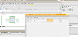
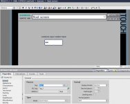
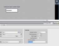
I need to make my Siemens PLC S7 (1212C) output one digital byte ..Q0.0 - Q0.7 (QB0) … output byte 0 … to represent any number from 0 to 255. The byte has to be written by the HMI.
The PLC's output will be sent to a Command Table's input, in a driver/controller for a linear motor. most of the lines in that command table have a curve instruction for that Linear Motor, which are simply, continuous sine waves. Different lines will produce sine waves of different amplitude, and period. That's it.
The work is done programming the PID driver/controller .. all that is needed, once the line number is selected on the HMI (example 27) .. is to have the PLC's QB0 output generate 0001 1011 … and the driver will run line 27's curve. How hard could it be?..
I was shown earlier on this forum that this is possible with the Siemens S7 1200 equipment.
I'm running TIA V11 SP2 update 5. This is a little problem because Siemens failed to make PLC 6ES7-212-1BD30-0XB0 ver 2.01 (1212C) updateable to ver 3.0 … Things are now a little squirrelly, but It looks like I can still program and run that PLC and HMI (6AV6647-0AD11-3AX0) KTP600 Basic Color PN
The Forum gave me lots of good starting places to focus my training on HMI programming for this project. This is all for a personal project.. I'm not employed to do motion engineering, I just want to understand this work as much as possible. I should hire a programmer; however, I don't know how to do that yet…
If you could recommend someone near Fallbrook, Calif, that would be great. Better still, If there's just a few steps here, I would greatly appreciate a mini tutorial on a simple program for the HMI .. very simple! … I can always expand and improve as I study all the YouTube tutorials, and manuals on HMI programming. I'm doing fairly good at programming the PLC.
Regards, Michael
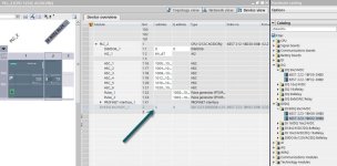
PS: I've added a SM1223 I/O module, (6ES7223-1BH32-0XB0) so that's probably the best destination for the 8-bit binary word from the HMI.


