N7 bits

stvsas

Member
Join Date
Feb 2004
Location
leominster, Ma
Posts
75
Help!! I just uploaded a file from a Micrologic 1000 and there are many lines that have N7 bits as inputs and outputs. I've never run across anything like this before. Is this some form of indirect addressing? I'm hoping someone here has an answer. Thanks in advance for any help I get. This is a great site!

stv
 
no, this isn't indirect addressing ... it's just Allen-Bradley's way of storing integer values ... the "N" sort-of-kinda stands for "integer" ... but since the "I" had already been assigned to "Inputs", they used "N" for "integer" ... think of it like a variable in algebra ... just as X can be equal to 4, N7:0 can also be equal to 4 ... in fact, you can store any whole number (no decimals allowed) in an integer as long as you stay within the values -32768 and +32767 ... try doing some simple MOV (Move) commands to experiment ... push a button and MOV the value "123" into N7:0 ... push another button and MOV the value "321" into N7:0 ... try to MOV the value of N7:0 into N7:1 ... try some GRT (Greater Than) or LES (Less Than) instructions too ... play around and you'll get the hang of it ... and incidentally, don't call N7:0 a "bit" ... actually it's a "word" made up of 16 bits ... if you want to see the bits inside the word, try changing the "radix" on the data table window back and forth between "binary" and "decimal" ... note: you CAN access the bits in an integer like this: "N7:0/3" ... the "/" (slash) indicates that what follows is the address of a bit ...

hope this helps ... gotta go cut the grass ...
 
In addition...........

I just uploaded a file from a Micrologic 1000 and there are many lines that have N7 bits as inputs and outputs.
Don't get yourself confused about what an input or output is on the AB hardware. Inputs are addressed as I:x/xx and outputs are addressed as O:x/xx much as Ron indicated in his reply. What you are seeing I believe is the use of N7:x/xx bits for whatever the purpose was the original programmer intended. The N7 bits, as with any other bits, my be addressed using the
---------] [----------, -------------]/[-----------, and the -----------(   )-----------

which are XIC, XIO and OTE respectively. The use of these instructions or any others to address bit level data, in no way implies that they are inputs or outputs. Only those bits in the Input/Output portion of the data table are actually real world I/O and are addressed to the same exact instructions as I listed above. Take a look at the AB programming manual for the M/L or SLC or other processor and see just what these instructions are intended for.
p.s. There are many areas of the data table that may be used for either word or bit storage. The B3 file is a good example of a file that gets used for both purposes quite often.
 
Last edited:
Let me see if I can make myself a little clearer. The N7 bits are used as contacts and coils, just as inputs and outputs or B3 bits would be used. And the N7 file uses the decimal.


N7:0/1 N7:100/9 N7:1/7
----] [----------]/[----------(L)-----

This is an example of a line of code. I went to the N file and it is in decimal. And there is no N7:100/9 bit in decimal of binary. I'm confused!
I do wish to thank you for all the answers so far, but I'm still confused. Does this make the problem a little clearer?
 
In AB speak the B files are usually used for bits ie B3:0/1
ie binary file 3 word 0 bit 1
wheareas the N files are used to represent whole numbers
ie N7:0 = 23543

If you want to you can use the value of the whole B3:0 word ie in an unsigned state the 16 bits can represent a value from 0 - 65357 or somewhere around that.
You can also us the bits of an integer to represent bits ie N7:0/3 is the 4th bit of the word N7:0. You can set the individual bits of an integer file with an OTE or OTL. That is to say you can use the individual bits in lieu of binary file bits.

Personally I try not to use N bits this way but quite often I set different bits of a B word then run a NEQ to perform an action if B3:0 is not equal to zero.

To explain a bit better I might wish to turn on a valve from 7 different actions or events so for each event I OTE B3:0/0 or OTE B3:0/1 etc. Then I have 1 rung with a NEQ B3:0 to zero OTE O:0/1

The reason for the NEQ and not a > than is that it allows the full 16 bits. If I OTE B3:0/15 then the value is negative and the output would not turn on.
It is possible to just put the all the XIC in the rung but this is a much neater way.

As someone earlier earlier in the post explained, fire up RSLogix type a number into N7:0 and view the data table with different radix views, it will become clearer. Regards Alan Case
 
Relative terms?

Let me see if I can make myself a little clearer. The N7 bits are used as contacts and coils, just as inputs and outputs or B3 bits would be used
Everyone who has answered knows this!

And the N7 file uses the decimal.
Ditto from above!


N7:0/1 N7:100/9 N7:1/7
----] [----------]/[----------(L)-----


This code line reads as: if N7:0/1 is on or a one, and if N7:100/9 is not on or a zero, then latch N7:1/7 or turn on that bit or make it a one whichever you understand best.
Now, as to why anyone would use N7 bits in this fashion and not use lets say B3's, I have not a clue. Although I have seen it done many times and suffice it to say it is just fine to do.

I went to the N file and it is in decimal. And there is no N7:100/9 bit in decimal of binary. I'm confused!
I believe you are confused mostly over what a bit is and what a word is. All the files in all PLCs are made up of words in a memory organized to suit the design of the particular machine. AB uses the data table concept to organize its file structure for all things data that are needed by the unit and the programmer. Taking the AB SLC family for example, they use 16bit words organized as various data types. These are; I for input, O for output, B for binary, or some call them internal relays, and the infamous N register you are perplexed by. "N" is used mostly to store iNteger numbers in decimal form but you can store any number up to 32767 in there in the most convenient form you need to use including binary, hex, or octal. That does not change the fact that the words are still 16 bits each and that to access the word in your program you address it as N7:0, or N7:100 or whatever the address is you need to use. Now, within each word, lets use N7:100 there are 16 bits available if you want to address them. These bits are N7:100/0 through N7:100/15. To address these or any other bits in the memory, you have to us an instruction that is made for bit level addressing. Example the XIC ------] [------ or the OTE -------( )-------- depending on what information you want or action you want to take.
I believe studying the AB manual for your processor will help and you might try downloading the LogixPro software from The Learning Pit as it is a really good tool for learning AB PLCs.
 
I've only used AB a few times but I think what you need to understand is the relationship between integers and binary.

If AB is the same as Siemens then, although N7:0 is holding a word, you can still use the various 'bits' of that word on bit level.

Let me explain a little and if I'm wrong with this then I'm sure one of the more experienced AB programmer will let you know to ignore this post... however, as I understand it...

N7:0/1 N7:100/9 N7:1/7
--| |-------|/|---------------(L)

We have established that N7:0 holds an integer ie a whole number.

If I load a 13 (for example) into N7:0

Then N7:0 would look like this (in binary)
0000 0000 0000 1101

So the bits that would be on would be: N7:0/0 N7:0/2 and N7:0/3

So, in your example above, if we assume that we have nothing in N7:100, then if we loaded (or moved) a 2 into N7:0 then N7:1/7 would Latch in.

As I said right at the start of this post, I'm only assuming that this is the way that AB does it, I'm a lot more familiar with Siemens but it sounds logical to me.

Try to get your head around the relationship between bits and words and the value of those words in Base 10 (ie. Decimal)

;)
 
N7 and B3 files are identical in every way except that when you
open them, default view for B files is binary and for N files is decimal.
You don't like the default view? in lower right corner of the
data table window is radix. Select view you prefer. If you want to
see N file at the bit level instead of decimal, just change radix to binary.
 
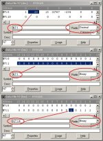
maybe this will help ...

here are three different ways of looking at the very same information ...

[attachment]

in the top window, the blue highlighted area is the word N7:1 ... this word currently contains the value 23 ... in the second window, the highlighted area is still the word N7:1 – but now (since the radix has been set to “binary”) you can see the 16 individual bits inside the word ... in the bottom window, we’ve clicked on just one of the bits in word N7:1 ... this highlights just the one bit in blue ... the address of the bit is N7:1/4 as shown in the little red circle ...

you said:
And there is no N7:100/9 bit in decimal of binary.
here’s something else that might help ... put your cursor on the address N7:100/9 in your program ... click the right mouse button ... select “Goto DataTable ... ” from the menu ... the software should take you right to the bit and even shift the display into the “binary” radix mode on the way ...

n bits.jpg
 
Last edited:
I often use N7 whole words to represent a device.

N7:0/0 auto
N7:0/1 fault
N7:0/15 interlocked

etc...

Then in your HMI application you can use the decimal value of the
word for color schemes. Green = automatic and open
yellow = manual and open etc...
 
Using bits from an integer is handy when you are communicating between PLCs. For example, I often use one word of an integer for the status bits. Then I can include them in the same read or write block as the process data, and just look at the individual bits for On, or Fault, or whatever. That saves having a separate message block for just the bits.
 
Tom, you are right mate.

I once did a job on a filler CIP system and the software had to turn on and off a lot of valves.

I just had sequential bits turning on each valve output and then I loaded in different integers into a word and it switched the outputs on and off.

Much better than having a load of OR conditions prior to each valve output.

:)
 

Similar Topics

Hi I am being given several fault words (as a DINT) from a Drive that I am receiving into a Compactlogix L33ER controller. I have a small...
Replies
12
Views
1,135
Dear Fellows; I am working on a very old machine which is designed in GE 90-30 PLC system. I have some difficulties like 1. How a force to...
Replies
3
Views
334
Hi All, I am trying to write some simulation logic for an existing project im working on. Does anyone know if this is possible to write to...
Replies
6
Views
1,273
Hi, I have this code: LAR1 P##structy L 0 T LW [AR1,P#0.0] which resets all the bits in this struct called structy...
Replies
1
Views
639
I am passing DINTs between a Micro800 and CompactLogix - each bit in the DINT has its own unique meaning. On the Studio5000 side I can just write...
Replies
3
Views
1,080
Back
Top Bottom