rankhornjp
Member
Processor: Modicon Quantum 652 60
Software: Unity 7.0
Language: LL984
Equipment: Extractor (basically, a large drag conveyor)
Input: Level transmitter in hopper
Output: Speed of extractor motor
Current programming: First PID2 loop is on when extractor is started. SP is 60% hopper level. This is tuned more aggressively than the second PID2 (P gain of 1). This PID2 will run for a minimum of 1 hour. During this hour an average block is calculating the average speed of the OUTPUT. Once hopper level is +- 15% of SP for at least 1 hour, the control moves to the second PID and clamps the output at +-5% of the average. The second PID2 is less aggressive so the speed swings a LOT less (P gain of .25). The second PID2 will stay in control as long as the hopper level doesn't go +-20% of SP (in this case, greater than 80% or less than 40%). If this happens, control switches back to the first PID2 and we start over from the beginning.
We are trying to smooth out the output of product from the extractor so that everything down stream will run smoother. If you run the extractor at a steady speed the hopper level will oscillate and sometimes the hopper will fill up too much or empty out (which is just as bad). So that is why we are using the second PID2 to lessen the oscillations, but allow it to adjust the speed in a smaller range to prevent overfilling the hopper, or running it empty.
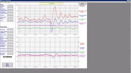
Problem: When control shifts from the second PID to the first PID I get a huge jump in extractor speed. This is bad because it will increase the load (amps increase by ~40%) on the conveyor that the extractor dumps out onto (if hopper level is high).
Is there a better way of accomplishing this? If not, how can I prevent the large jump in output when the PIDs change?
Pic attached to show extractor trend during change. This shows a change from hopper level being too low.


