Need help to write a PLC code using Melsoft GX Developer

sumon

Member
Join Date
Aug 2014
Location
Saitama
Posts
5
Hi every body. I am new here also very new in PLC coding.
I need to write ladder code for the following conditions.

1. When you press the button switch PB1(X0) ,then the lamp PL1(Y50) is ON.

2. When you press the button switch PB2(X1) ,then the lamp PL2(Y51) is NO.

3. When you press the button switch PB3(X2) ,then the lamp PL3(Y52) is ON.

4. When the button switches PB2(X1) and PB3(X2) press at a time (same time) , only the lamp PL1(Y50) gets ON.

5. When the button switches PB1(X0) and PB3(X2) press at a time (same time) , only the lamp PL2(Y51) gets ON.

6. When the button switches PB1(X0) and PB2(X1) press at a time (same time) , only the lamp PL3(Y52) gets ON.

7. When the button switches PB1(X0), PB2(X1) and PB3(X2) press at a time (same time) the all lamps (PL1(Y50), PL2(Y51) and PL3(Y52)) flash or blink (1 second ON OFF).
 
If you use a coil-instruction:

3 outputs ---> 3 rungs


Think about it, try and if you need more help:

please post some screenshot of your homework. People in this forum like to see that you made some effort before asking this kind of questions.
 
Last edited:
X0
----II----------------(Y50)--

Here is a start for you, see if you can figure out the rest, see what you can do then ask for help if needed.
 
3 outputs ---> 3 rungs
It seems that for the last Step 7 timing function, there is an option to use a 4th rung that has either a clock bit or 2 parallel timers. The alternative would be to use a 3rd parallel branch on each of the first 3 rungs.
 
I am thanking to ivo, Badger and Lancie1 for there kind advice specially about 'home work first'.

I have already done some home work for condition 1-6, but I have stuck at condition 7.

First I have made 6 different logic math for 6 condition (not condition 7)

x0x1'x2' = Y50Y51'Y52'.........1
x0'x1x2' = Y50'Y51Y52'.........2
x0'x1x2 = Y50'Y51'Y52..........3
x0x1x2' = Y50'Y51'Y52..........4
x0x1'x2 = Y50'Y51Y52'..........5
x0'x1x2 = Y50Y51'Y52'..........6

from 1 & 6
(x0x1'x2' + x0'x1x2)Y51'Y52' = Y50 -----(i)
from 2 & 5
(x0'x1x2' + x0x1'x2)Y50'Y52' = Y51------(ii)
from 3 & 4
(x0'x1'x2 + x0x1x2')Y50'Y51' = Y52------(iii)

from these new three equations I can meet first 6 condition.
But, in accordance with Lancie1 I am confused about condition 7:confused::confused::confused:
 
But, in accordance with Lancie1 I am confused about condition 7
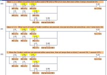
Here is one way to do all Steps, including Step 7. This was done using the LogixPro Simimulator software, but you should be able to write a similar program in Melsoft GX Developer.

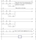
Another method would be to add Rung 003, with 2 timers, 1-second ON time, 1-second OFF time. Then use the ON timer bit in place of the S:4/9 internal clock bit.

Sumon's Problem- Switches & Lamps.JPG
 
Last edited:
Thank you Lancie1!
This attached ladder diagram gave me some senses, but not much as I am a beginner.
I am searching good tutorial (problem $ solution) on Melsoft GX Developer. I need to build up good sense on ladder coding using it.
Can you also let me know where I can find demo version of Melsoft GX works2 Developer?http://www.plctalk.net/qanda/member.php?u=3696
 
This attached ladder diagram gave me some senses, but not much as I am a beginner.
1. The top branch of rung 000 does Step 1.
2. The top branch of rung 001 does Step 2.
3. The top branch of rung 002 does Step 3.
4. The 2nd branch of rung 001 does Step 4.
5. The 2nd branch of rung 002 does Step 5.
6. The 2nd branch of rung 003 does Step 6.
7. The 3rd branch of rungs 000, 001, and 002 does Step 7.

Can you also let me know where I can find demo version of Melsoft GX works2 Developer?
I do not know.
 
The best I can design, this would be the Mitsubishi GX Developer version, using the Special Timer function STMR. I may not have the STMR set up exactly correct, because I have never used it before.
 
@Lancie1, I am again thanking you for your nice and kind effort.
I have already done the ladder logic that exactly similar to your design except the blinking part, soon I will upload that.
 
Well done. Post your version when you get it working. Be sure to add rung comments to help explain what it does and how it works.
 

Similar Topics

I need help writing a plc lab ladder diagram for class. Can anyone help? Please!!!!!!!! Its a clamp and grind.
Replies
34
Views
6,494
Hi, every body! I have a small project. I wrote programmer control two pump motors by plc s7-300. Now I want to write programmer connect PLC to PC...
Replies
3
Views
5,402
I have a auto-start button with the function with the coding of the following: FUNCTION StartAuto() INT Counter = 0; WHILE Counter <...
Replies
8
Views
6,554
Hello nice to meet you, im new in here, I'm currently trying to convert code written in STL for a S7-400 to SCL for an S7-1500, because when i run...
Replies
5
Views
292
Back
Top Bottom