Lesser of 2 Evils

Tim Ganz

Member
Join Date
Dec 2010
Location
Dallas, Texas
Posts
689
I have to run a T/c to an oil tank on an existing machine, This will be to read the tank temp in the plc to set a high limit alarm and it will display the tank temp on the HMI.

I have to use existing conduit paths.

Option 1 Path would be 12 feet from the tank and would be T/C with built in transmitter giving out a 0-10 DC signal which would connect to a devicenet analog input block. Part of this conduit has wires for 1/2 motor at 120 ac as well as 120 Ac and 24 dc control wiring.

Option 2 path would be 35 feet from the tank and would be a plain T/C with T/C extension wire going through the same conduit described in option 1 but would land on a devicenet J type T/C input block. T/C extension wire would be twisted and shielded.

This is not good either way but there is no other choice. Which would produce the best result and which would be the lesser of 2 evils?
 
If you have to use that conduit then you will get better results with a 4 to 20 ma signal
instead of 0-10v. And make sure you use shielded wire.
If you analog input card is voltage only then developed the voltage across a 250 ohm resistor at the analog input card.
 
Looking at the situation again it looks like I am going to be forced to use the twisted and shielded tc extension wire. How bad are the 120 volt motor and controls and 24 dc wiring going to effect this?
 
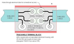
A shielded cable theoretically eliminates the noise. The problem is at the termination points on each end - no good way to shield those.

Unless some company decides to make a thermocouple verison of my True-Shield Terminal Block.

TRUE-SHIELD TERMINAL BLOCK.JPG
 
Last edited:
What code violation are you referring to?

It is not best practice, but I don't see the code violation. As long as all the conductors in the conduit have an insulation rating sufficient for the highest voltage then code is satisfied. Code doesn't regulate signals.

That 1/2 HP 120 Volt motor is a potential problem. Large currents mean larger magnetic fields, which means more crosstalk. I don't have enough information to say what that motor current is but I expect it is somewhere around the 10 amp range. Alas, if only it were as easy as HP*745watts*HP-1/120V. Single phase motors vary a lot in construction and efficiency and typically draw considerably more current than is yielded by dividing the hp (in watts) by volts.

So a twisted pair cable, preferably shielded should definitely be used, and the total exposure distance should be kept as short as possible. Using a 4-20mA signal instead of a micro-volt T/C signal also will help. If there is a reasonable way to separate the signals from the motor wiring then it should be done.
 
What's wrong with the 35 foot option? I have run thermocouple signals 75-100 feet with no problems using proper wire and connectors. Mine were armor jacketed for environmental reasons and not near power wiring.

If you have to share pipe with power and switching control signals, then use a 4-20mA transmitter and you should not have signal noise problems, but "should" is not a guarantee. If you try to use the millivolt (raw thermocouple) signal or the 0-10vdc signal, you may get away with it, problems may arise over time and be difficult to cure. I would go for the separate pipe and pay a small price now rather than gamble on what it might cost later if you run into trouble.
 
What's wrong with the 35 foot option?

Option 2 path would be 35 feet from the tank and would be a plain T/C with T/C extension wire going through the same conduit described in option 1 but would land on a devicenet J type T/C input block. T/C extension wire would be twisted and shielded.

Because it is in the same conduit as option one.(120vac)(n)
 
Thanks, Keith. I did not know those existed. I knew there was a need, and now here is the solution, at least for thermocouples! Now maybe some company will make a terminal-block version for regular old analog signals.
 
Back
Top Bottom