signal isolator

GEOFRA

Member
Join Date
Jul 2002
Location
Nicosia
Posts
99
Can anybody help with a schematic on how to connect a loop powered sensor(sinking or sourcing) to the input of a signal isolator and from the output of the isolator to the analogue input of the PLC?
 
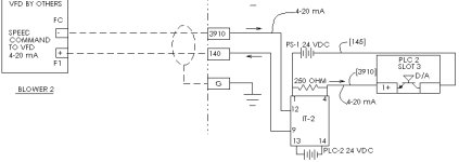
HEre is one example. There are lots of variaations, depending on manufacturer and model. Check the suppliers data for your specifics.

scratch.jpg
 
Tom thank you for the schematic but it has confused me.
What I have is a sensor that needs to be powered from the loop as it is not connected to an instrument or transmitter.
Then I have a signal isolator which has +,- IN and +,- OUT and then I have the +,- IN of the PLC.How are all these connected together?
 
What make and type of PLC analog input module do you have ?

An isolator is not allways required.
You need to provide 24VDC on the supply terminal of the sensor (sometimes marked "+").
From the output terminal on the sensor (sometimes marked "-") you can go directly to the analog input card.
The analog input card must have its "GND" terminal connected with the 0VDC of the power supply that generates the 24VDC for the sensor.

Only if the application requires isolation, or if you need to change the signal from 4-20mA to f.ex 0-10V do you need a converter (aka. amplifier or isolator).
 
The Module is an EM231 from SIEMENS s7-200 series with 4 Analogue inputs.
I would like to introduce a signal isolator between the pressure transmitter and the Analogue input.I would like to know how to connect all things together without loosing the isolation.
 
I will try to explain this in text:

An isolator will sit in the middle so to say.

To one side of the isolator will be the transmitter.
It is possible that the isolator can provide 24VDC power for the transmitter, but in most cases you need to supply 24VDC from a common 24VDC source. The signal then enters the isolator.

On the other side of the isolator will be the analog input.
If you want full isolation, then there must be two connections (+) and (-) from the isolator to the analog input, and the analog input must be "differential".
If on the other hand you can accept that the system shares a common ground, then you can connect the (+) line to the analog input, and the analog input must be "single-ended". The analog input and the isolator must then have the same ground potential.
The latter option is not true isolation, but it will still protect the analog input against strange voltages or wrong connection of the transmitter.
 

Similar Topics

I'm needing to get a Signal Isolator / Splitter but needing quickly so my normal 1 Channel Input and 2 Channel Output version I would use is not...
Replies
6
Views
2,893
I am not sure why this is requested, but it was asked. Currently I have one PLC , with one output to a relay, turning on a field equipment (just...
Replies
7
Views
215
Hi, I am working on automating an industrial fabric shrinkage tester to replace its outdated electronics with a PLC. To get the tank's water level...
Replies
14
Views
536
Hello, I have a compact Logix plc and I have been task with configuring alarms into our SCADA when an Analog signal stops moving. The analog...
Replies
6
Views
239
Hi I have an old panel builder 32 that I’m replacing for a factory talk me hmi . In the plc for the old panel builder there is a coms bit for the...
Replies
0
Views
74
Back
Top Bottom