Newbie Micrologix1000 Analog Q

Thunderbike

Member
Join Date
Jan 2014
Location
New York
Posts
12
Ihave a machine with a failed Moeller PLC that I have no documented logic for, and am replacing with a micrologix 1000 1761-L20BWB-5A. Most of my experience with RSlogix (and other programs) is in diagnose, repair and minor tweaking of machines. I have written most of the required logic I need on this 1000 using the simple drag and drop "user" menu. I now have to set up the analog portion and am flat out lost! I have a hyd valve that controls speed using 0-10V input. There was a 20K pot used as an analog input, and the output controlled the valve. I am totally in the dark, and dont even know how to find or address the analog inputs and output. could someone walk me thru this PLEASE? this is soooo much different than the SLC 500 I'm used to working with.
thanks
 
I forget if micro 1000 uses the SCP instruction but that's what you need to do. Scale the 20k pot to the 0-10v output for the valve. Does that sound right?
 
I am totally in the dark, and dont even know how to find or address the analog inputs and output.
I can read the MicroLogix 1000 Programmable Controllers User Manual, Chapter 5 to find those addresses for you.

Analog Output (1 each)
O:0.4 (Voltage or Current)

Analog Inputs (4 each)
I:0.4 Analog Input 0 (Voltage)
I:0.5 Analog Input 1 (Voltage)
I:0.6 Analog Input 2 (Current)
I:0.7 Analog Input 3 (Current)

I forget if micro 1000 uses the SCP instruction but that's what you need to do.
No, but it does have the SCL (Scale Data) instruction that can be used to scale the analog inputs and output.
SCL [Scale Data]
Rockwell Software

Description
Use this instruction to scale data from your analog module and bring it into the limits prescribed by the process variable or another analog module. For example, use SCL to convert a 4-20 mA input signal to a PID process variable. Or use SCL to scale an analog input to control an analog output.
When rung conditions are true, this instruction multiplies the source by a specified rate. The rounded result is added to an offset value and placed in the destination. You can use indexed or indirect addresses for the source or destination parameters.

Equations used in calculating a linear relationship:
Scaled value = (input value x rate) + offset
Rate = (scaled max. - scaled min.) / (input max. - input min.)
Offset = scaled minimum - (input minimum x rate)

Entering Parameters
Values must be between -32768 and +32767 for the following parameters.
Source must be a word address.

Rate (or slope) is the positive or negative value you enter divided by 10,000. It can be a program constant or a word address.

Offset can be a program constant or a word address.

Destination is the address of the result of the operation.
 
Last edited:
Thanks, I have that printed, but I don't think you understand how little I know about programming this. Everything I've done has been drag and drop. I'm not sure where in the program I go to make those addresses work, or how to build a rung with the info. I'm an electrician very comfortable with repairs, but am as dumb as a rock with programming. RSlogix makes simple relay type programing easy without having to "write" logic. Not so with the analog portion of this 1000
 
Thanks, I have that printed, but I don't think you understand how little I know about programming this. Everything I've done has been drag and drop. I'm not sure where in the program I go to make those addresses work, or how to build a rung with the info. I'm an electrician very comfortable with repairs, but am as dumb as a rock with programming. RSlogix makes simple relay type programing easy without having to "write" logic. Not so with the analog portion of this 1000

is your pot directly controlling the valve?
 
Thanks, I have that printed, but I don't think you understand how little I know about programming this.
No, your first post indicated that you were a beginner. You will have to know how to read and understand the user manuals in order to do this type of work. No one will be there standing over your shoulder to tell you every step, so first you have to learn how to learn by reading.

I'm not sure where in the program I go to make those addresses work, or how to build a rung with the info.
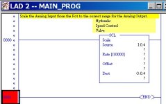
Okay, here is a rung to start you off in the right direction. The Destination Output is your goal, what you want the PLC to DO for you.

Hydraulic Speed Control- ThunderBike.JPG
 
Last edited:
Luke, no, I wish it was! The pot was run to an analog input, then the valve is operated by a 0-10V analog output. Its a very basic setup and a very "coarse" adjustment.
Yea Lance, I need to, and really WANT to learn all of this. 35 yrs of industrial electric,machinery repair, hydraulics, pneumatics, VFDs, servo and stepper motors, certified welder, fabricator, class A license, all go to show I love to learn. That being said, this is not a hobby project, and I need to get this thing up and running. I'm one input and one output from getting this machine back online, so I'm here asking,even if inappropriate, for someone to "stand over my shoulder" for this one or two rungs. THEN I will be looking into a lesson plan so I'm not in this position again. RSlogix allowed me to get away without knowing the language (as did Siemens and Mitsu) long enough


'
 
I have written most of the required logic I need on this 1000 using the simple drag and drop "user" menu.
ZIP and attach the RSL program that you already have, if you want a complete working program.

Also we need to know how the old pot was wired into the input logic (how the pot resistance was converted to the 0-10 volt range). If you have that already handled, so that you have an input of 0-10 volts DC, then the scaling may not be needed at all. A simple MOVE instruction may do the job.

Lance, Is the [SCL?] available in this 1000? Ive done some analog in the SLC500, but the 1000 shuts me out of a lot of options
Yes, that rung is from a MicroLogix 1000 Analog PLC program that I started just for you.
 
Last edited:
I'd like to add, the Micrologix 1000 Analog I/O has 10-bit resolution. What that means is, the addresses associated with those inputs and outputs will show a number between 0 and 1023 to indicate the signal level. If you apply 10 volts to the first analog input channel, the address value of I:0.4 will be 1023 (or something close to it). If you apply 5 volts it will be 512. If you apply nothing it will be 0. The output is the same, write a value of 1023 in O:0.4 and it will put out 10 volts. write 512 and it will put out 5 volts.

The SCL instruction in Lancie's post converts the values from your input channel to a value that makes sense to you. So if you wanted to see the value in terms of 0-100%, you would have to figure out the slope of the line (rise over run) and the offset. So, for example, let's say you hook the pot up, turn it all the way down and you see a value of 10 in I:0.4 (remember, these aren't exactly accurate). Let's also say you turn it all the way up and see a value of 512. This might be because of your pot or whatever other device you hooked up to it. That's okay. As long as the number changes when you move the pot. So in a span of 0-100% open (the "Run"), you have a "rise" of 502 counts (512-10). The SCL instruction expects a Rate value, so what you would do is divide 502 by 100 (rise over run). The answer is 5.02. The Rate parameter does not accept floating point numbers, so we have to multiply the answer by 10000 to get the accuracy we need. And that gives us the rate, 50200. The Offset is just the value of your input when it's at 0%, so you'd put a 10 in there. The destination would be an integer type address like N7:0. So now, when you turn the pot, the value in N7:0 will go from 0-100.

Controlling the valve works the same way but in reverse, you'll need to translate the input signal to a 0-1023 value using another SCL instruction.

Hopefully this can get you started.
 
Lancie and Factory, thanks, I think I will study more over the weekend and attack it 5 am Monday!
I have ZERO info on how they programed the old plc. I only can see that the pot was wired into an input and and the output was connected to a proportioning valve controlled with 0-10v. This is a very crude setup that is only a slow down stage before stopping a small cylinder so it doesn't slam, and 20 or 30% difference is unimportant.

You don't necessarily need to know how they programmed it. What you need to know is how it's supposed to work. So the valve always follow the pot, or does the pot control a "slow-down" level where it only reads it for part of the cycle? That's going to make a difference.
 
OK, the valve always follows the pot. The speed is set with the pot and left alone forever ideally. The end game is just a fixed speed
 
OK, the valve always follows the pot. The speed is set with the pot and left alone forever ideally. The end game is just a fixed speed

Cool, that makes it simple then. If your pot input does range pretty close to 0-1023, all you need to do is use a MOV statement instead of a SCL. Move the value of I:0.4 to O:0.4 on an unconditional rung and you're done.

If it doesn't, then your run is going to be 1023, your rise will be the difference between the input min and max value (max-min) and your offset will be the value of your input when the pot is at 0. Your destination address will be the output address O:0.4. Either way this is just a one rung solution.
 

Similar Topics

Hello all, I'm a new member here. I've joined as I want to learn about PLC programming. I've got a few questions to begin with. To get me...
Replies
37
Views
4,523
Howdy folks. Been doing PLC programming for like 15 years now in LD and ST, but I'm trying to learn SFC now and have a kind of dumb question... I...
Replies
4
Views
1,373
Hello. New to Unity and had a couple quick questions. Can a Modicon M340 output to a small multiline LCD screen and not a full HMI?
Replies
4
Views
956
Hi. I'm learning AOI programming in RSLogix 5000. I created an AOI with several input and output parameters but when I choose the AOI in the main...
Replies
17
Views
3,184
Good morning, I've had an inverter fail with firmware revision 5.002, the only spare is Rev 7.001, when updating the project with the new...
Replies
2
Views
1,257
Back
Top Bottom