Direct Logic 05 to sense shaft stall with proximity switch

kasch

Member
Join Date
Oct 2014
Location
MN
Posts
7
I have a Direct Logic 05 series D0-05DR-D PLC. I need it to sound an alarm to the machine operator if a rotating shaft stalls. This is my first PLC project, I am struggling on the program. I have a NO machine engage switch to activate it on input X0, a N0 prox switch on two different shafts to sense the stall/slowing condition of the machine on X1 and X2, and a alarm buzzer on output Y0. The shaft that sensor X1 is on rotates much faster (about 1000 rpm) than the shaft monitored by sensor X2(about 500 rpm)

I am using DirectSOFT 5 to create a program, with a one shot, and a timer on delay to turn on the alarm when the timer runs out, but can not figure out the correct way to lay out the program. The software will not let me insert the one shot in the middle of the rung? Can someone please help by drafting up a program to do this? I need the machine alarm system functional ASAP!!
 
The best way you can get help on the forum is to zip and post your files even if they don't work. That way we can correct the problems and re-post a working solution. Putting ASAP!! in your post only tends to upset folks here so that no one will want to help you. This is an all volunteer forum, no one gets paid to help others out.
 
Here is one suggestion to solve your problem of using a one-shot (PD) instruction in the middle of a rung.
Create a rung that uses only the input that you want to one-shot and at the output of that rung use a PD coil. Use the address of the PD coil on a contact in subsequent rungs wherever you need that one-shot.

Edit:
Make sure your sensors are capable of switching off and on at the rate you are trying to sense.

2nd edit:
I'm not certain that you even need one-shots for the inputs. You could use two timers on two rungs timing the two states of the X1 sensor (on/off), and you could use two timers on two rungs timing the two states of the X2 sensor (on/off).
 
Last edited:
I am using DirectSOFT 5 to create a program, with a one shot, and a timer on delay to turn on the alarm when the timer runs out, but can not figure out the correct way to lay out the program.
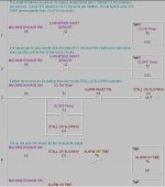
Here is one way to lay out the program that will work. I could not get all of the program in the screen shot, but I am sure that with a little study, you can figure out the rest.

Shaft Stall DL05- Kasch.jpg
 
If there is significant acceleration time you may wish to delay triggering the alarm for a certain period of time or, at least, prevent the latching of the alarm.
 
I have a Direct Logic 05 series D0-05DR-D PLC. I need it to sound an alarm to the machine operator if a rotating shaft stalls. This is my first PLC project, I am struggling on the program. I have a NO machine engage switch to activate it on input X0, a N0 prox switch on two different shafts to sense the stall/slowing condition of the machine on X1 and X2, and a alarm buzzer on output Y0. The shaft that sensor X1 is on rotates much faster (3150 rpm) than the shaft monitored by sensor X2(800 rpm)

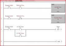
See attachment for the program I have been testing. I don't get any errors, but my X2 input light on the 05 stays lit dimly at all times, and gets brighter when the prox senses steel. Does this sound correct guys, or do I have bad prox switches? I am only testing right now with one input (X2). Does anyone see any issues with this program? I want the alarm to sound at all times if it sees low RPM on either input. The alarm should silence when the machine switch is off in this program, am I correct?

Capture.jpg
 
I don't get any errors, but my X2 input light on the 05 stays lit dimly at all times, and gets brighter when the prox senses steel.
Check to make sure you have the prox switch wired correctly. If so, then the dim state is proably caused by leakage current. You can fix that by adding a load resistor to soak up the leakage current. See this post:
http://www.plctalk.net/qanda/showthread.php?t=75474&highlight=LED+load+resistor

Does anyone see any issues with this program?
Yes, you did not add documentation about how it is supposed to work. You did not add descriptions for each address. For 800 RPM, your timers need changing. 800 rotations per minute /60 seconds per minute = 13.33 rotations/second. 1/13.33 = 0.075 seconds per rotation. So set your timers to greater than 7.5 x 0.01 seconds, or "8".

I want the alarm to sound at all times if it sees low RPM on either input.
A constant-ON alarm is always a mistake. It is very irritating if the alarm horn or buzzer is very loud. It is much better and less irratiting to use an on/off alarm. An oscillating or warbling alarm can be heard for the same distance, and actually is even more noticable out of the typical loud hum of an industrial plant. Many loud irratitng continuous alarms get knocked off the wall by fed-up operators with large hammers.

Why must you use an input from 2 shafts? If they are mechanically connected, if one stops, they both stop. If one turns, they both turn. The only thing an extra input will tell you is that the gears for one shaft may have broken, an unlikely situation. The high-speed shaft will be more difficult to sense. 3150/60 = 52.5 rotations/sec. 1/52.5 = 0.019 seconds per rotation. Each ON period is probably no more than 1/10 of the total rotation time of 0.019, or about 0.0019 seconds. So your prox switch and PLC input will have to be able to sense a ON time of 0.0019 seconds. That could be a problem. You may need to use a high-speed counter input in order to have a switching speed equivalent to the on/off speed of the X1 shaft. Check to see if your prox switch and PLC input can do this fast switching.

EDIT: I checked the DL-05 manaual for you. In Chapter 2, Page 29, the chart shows that the DL-05 can detect ON and OFF periods of 4 miliseconds, or 0.004 seconds. That is longer than 0.0019 seconds, so you will not be able to use the standard inputs for the high-speed shaft. You will have to use the high-speed counter inputs X0, X1, and X2.

For the high-speed shaft, you might increase your prox target area so that it is equal to 1/2 the shaft diameter. Then your ON time would be increased to about 1/2 of 0.019, or 0.0095 seconds or 9.5 miliseconds. That would be more likely to be detected with a typical proximity switch and PLC input.

The alarm should silence when the machine switch is off in this program, am I correct?
Yes. But the alarm will also go off if the shaft is still turning. In other words, you have no seal-in contact on your Rung 3 that keeps the alarm on any longer than the 0.13 second cycle that created the alarm. So your alarm, once ON, may stay ON for only a short period, a few miliseconds before it is reset by the still-rotating shaft. If you want to be notified of shaft-slowing alarms (not just stalls), then you must seal in an alarm until reset by the operator, or maybe reset the alarm using another timer delay.
 
Last edited:
I don't get any errors, but my X2 input light on the 05 stays lit dimly at all times, and gets brighter when the prox senses steel. Does this sound correct guys, or do I have bad prox switches?
If the X1 input works correctly with the same type of wiring, then most likely your X2 prox is not completely switching OFF before the next ON target. In other words, the prox switching speed is not really fast enough to detect 3150 RPM. You need a faster input sensor for the X2 shaft - or come up with a good reason why you can get along without X2 in the first place.
 
Last edited:
kasch try this.

copy the text below and save so you can find it.

Open a new instance of Direct Soft, click on file, import program, find the file you just saved and follow directions.

Copy below this line

PLC 05

// Rung 1
// Address 0
#BEGIN COMMENT
"http://www.plctalk.net/qanda/showthread.php?p=610753#post610753"
""
"I am using DirectSOFT 5 to create a program, with a one shot, and a timer on delay to "
"turn on the alarm when the timer runs out, but can not figure out the correct way to lay out "
"the program. The software will not let me insert the one shot in the middle of the rung? "
"Can someone please help by drafting up a program to do this?"
""
"Sounds like you have some RS logix experience. Direct Soft uses a different approach for "
"oneshots. Here is one of them. Note the PD coil."
""
""
#END
STR X1
PD C0

// Rung 2
// Address 2
#BEGIN COMMENT
"This rung is to check if the timer is done (not) and the prox OS were active at the same "
"time. If the conditions are true then we have a need to un sealin the alarm bit for the "
"rethresh prox"
""
"Note: the placement of this rung is scan critical it needs to be between the OS output and "
"the timer"
#END
STRN T0
AND C0
OUT C10

// Rung 3
// Address 5
STRN C0
AND X0
TMRF T0 K13

// Rung 4
// Address 10
#BEGIN COMMENT
""
""
#END
STR X2
PD C1

// Rung 5
// Address 12
#BEGIN COMMENT
"This rung is to check if the timer is done (not) and the prox OS were active at the same "
"time. If the conditions are true then we have a need to un sealin the alarm bit for the "
"rethresh prox"
""
"Note: the placement of this rung is scan critical it needs to be between the OS output and "
"the timer"
#END
STRN T1
AND C1
OUT C11

// Rung 6
// Address 15
#BEGIN COMMENT
"When I calculate the speed of the shaft prox 19.04761904761905 mseconds per "
"revolution it appears that you will just barely be able to sense the high speed shaft. As "
"Lancie mentioned you will need to have the prox on time be equal to the off time. This "
"would mean that the nominal on time would be 9.5 mseconds. As long as the PLC scan "
"time does not exceed 4 mseconds you should be able to sense every revolution. "
""
"One issue might be that the coarseness of the TMRF, it only goes to 10 msecond "
"resolution (0.01 seconds) and scan time. If I have calulated the time per revolution "
"correctly and your scan time was 4 mseconds the worst case senario would be the shaft "
"speed could drop to 2516 rpm before an alarm is triggered. Best case would be it could "
"drop to 3000 RPM before an alarm is triggered. "
#END
STRN C1
AND X0
TMRF T1 K1

// Rung 7
// Address 20
#BEGIN COMMENT
"This is one way to deal with the issue (sealin) that Lancie mentioned. "
#END
STR T0
STR C2
ANDN C10
ORSTR
OUT C2

// Rung 8
// Address 25
#BEGIN COMMENT
"This is one way to deal with the issue (sealin) that Lancie mentioned. "
#END
STR T1
STR C3
ANDN C11
ORSTR
OUT C3

// Rung 9
// Address 30
#BEGIN COMMENT
"This rung will sound an alarm and silence it untill there is a new alarm"
#END
STRPD C2
ORPD C3
ANDN X3
OUT Y0

// Rung 10
// Address 34
END

// Rung 11
// Address 35
NOP


#BEGIN ELEMENT_DOC
"X0","EngageSw","",""
"X1","RetreshProx","",""
"X2","HighSpeedShaftPr","",""
"X3","AlarmSilence","",""
"Y0","alarm","",""
"C0","RetreshProx_OS","",""
"C1","HighSpeed_OS","",""
"C2","Retresh_Sealin","",""
"C3","HS_Sealin","",""
"C10","ReTMRNotandOS","","Rethresh Prox Timer (not) and OS"
"C11","HS_TMRNotandOS","","HS Prox Timer (not) and OS"
"T0","RetreshShaftTime","",""
"T1","HS_ShaftTimer","",""

#END
 
Thanks

Thanks for everyones help so far. This installation is actually on my self propelled combine harvester. I did not get the time to install the PLC into the machine for this harvest season, but plan to get this operational before next harvest season. The OEM alarm system is failing and I basically am replacing the OEM system with this PLC system to do the same thing and more. OEM components are over $500 to replace. This will do a better job, and for a lot less $. I could monitor other things with this PLC as well. As soon as I get this machine back into the shop to install this system, I am sure I will need more advice. Should I be mounting this PLC inside an enclosure to keep the dust out of it? The inside of the combine operators cab sometimes can become dusty. I was thinking about mounting it inside an enclosure, with RS logic recommended clearances, but worry about the PLC getting too hot. Any thoughts?
 
I be mounting this PLC inside an enclosure to keep the dust out of it? The inside of the combine operators cab sometimes can become dusty. I was thinking about mounting it inside an enclosure, with RS logic recommended clearances, but worry about the PLC getting too hot.
If the operator can stand breathing the dust, then the PLC should be okay. Keep it as clean as possible, but a little dry dust will not kill it. Wet dust turned to mud is a big problem for any electrical device.

The Automation Direct DL-05 is rated to operate at up to 131 degres F and up to 158 F while not operating. If your combine cab is air conditioned, then you could probably mount the PLC in a ventilated electrical box. If the dust is your big concern, use a NEMA type 12 gasketed dustight box, and add filtered ventilation air (filter, fan, and ducts or tubes).

The constant vibration of the cab may be a bigger problem than the dust or heat. You may need shock-absorber mounts for your PLC box.
 
Last edited:
Installation complete, now need more program help

After testing the attached program today, the alarm sounds when I accelerate the machine to full speed, and then it stays on? The exact opposite of my goal. I have exported the program I was testing with and attached it to this post, so it for more details. Should I be using the high speed input option for this project? If so, what changes need to be made to my program?

Like any other piece of mobile equipment, the machine is engaged with the engine at idle, then accelerated to full throttle before actually feeding crop into the machine. I don't mind if the alarm sounds during this short 1 second acceleration time, as the OEM system did. That way we know the alarm is functional at sensing the stopped and slower than normal rotating shafts.

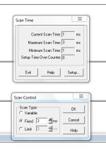
Also see the attached screen shot of scan control. This is where I set it to, is this correct?

milldrone, I was unable to get your program into DirectSoft6 for some unknown reason using file, import?

scan control.JPG
 

Attachments

  • VER1.txt
    2.4 KB · Views: 13
I don't see (although I did not look extremely closely) any mention made of changing your inputs to be capable of high speed.

I suggest you look at appendix E of the following (go directly to E-52, Mode 60: Discrete Inputs with Filter and change the filter time to 0 or 1 mSec.
 
I agree with what danatomega said.
Also, I'm guessing that your problem could be caused by the sensor response time being too slow. Please post the exact make and model number of the sensor. That should eliminate our guessing about that.
 
Prox info

Sorry, the prox info is listed in the .txt attachment, not the post.
They are Automation Direct # AM1-AP-1H with 2khz switching frequency, NO output and 0 to 2 mm sensing range, 12 mm diameter
 

Similar Topics

So this is my attempt at collecting and displaying data on a Cmore panel With a DL06. Each pair in my logic is the "Time total" or the TA15 and...
Replies
4
Views
477
Hello, I am having some trouble trying to use Port 2 on the direct logic (250-1) for K-sequence. I am trying to use RS-232, I have a breakout...
Replies
0
Views
549
I have a few o these controllers and had to replace a CPU. It looks like everything is there in the ladder including the registers for the port...
Replies
5
Views
1,459
Hey, I am entirely new to PLC's and am trying to help my friend with a project. He wants to take the signal from a PNP photoelectric sensor as...
Replies
12
Views
2,236
Anyone know anybody that will attempt a repair on a DirectLogic F1-130AR? There were a few hits on the internet but none I've used personally...
Replies
1
Views
1,289
Back
Top Bottom