Alternatives to output latch / unlatch

JeffLC

Member
Join Date
Apr 2014
Location
Ohio
Posts
5
Hi all,

I am programming a Micrologix 1200 to run an assembly machine for my business. This is my first experience programming a PLC and this forum has been invaluable in getting the machine up and running. My program uses output latch/unlatch commands to control pneumatic solenoid valves but I have read here these are generally not the preferred commands for what I'm doing. I also don't like how their retentive nature causes the air cylinders to move to their previous location when restarting after hitting the e-stop. I would rather they go back to the home position. I have been unsuccessful finding an alternative approach, however, and could use some help.

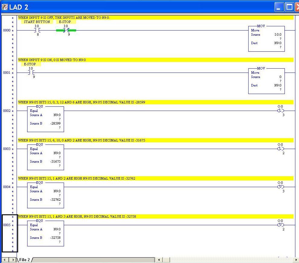
One of the main machine actions uses two air cylinders and two associated solenoid valves to move a metal bar. One cylinder moves the bar up and down while the other moves the bar left and right. The mechanism essentially draws a square with the bar. From the home position (lower left corner of square):

Energize output 3 (move bar up)
Energize output 2 (move bar right)
De-energize output 3 (move bar down)
De-energize output 2 (move bar left)
Repeat

This portion of the current program is attached. Any input on a better approach to the programming would be greatly appreciated. My knowledge of ladder logic is generally limited to examine if open/closed, output latch/unlatch, timers, and subroutines, so I'll need a little more detailed explanation than the more experienced programmers here.


Thanks,

Jeff

Indexer program.jpg
 
it's hard to say for sure without knowing more about your machine – but based on your following statement:

I also don't like how their retentive nature causes the air cylinders to move to their previous location when restarting after hitting the e-stop. I would rather they go back to the home position.

the solution shown below might answer your immediate needs ...

basically the S:1/15 bit will be True for just one scan whenever the processor first goes into the Run mode ... this will have the effect of UN-latching the output bits that you've shown us – and make these act as NON-retentive outputs ...

there are other ways – and you might like them better – so stick around and get some different suggestions - but I've got a hunch that you'll like the results you'll get from this simple fix ...

on the other hand, if resetting your E-Stop system does not cause the processor to "restart" (as if recovering from a "power-off" condition) then you'll have to go further than this ... tell us more about how your E-Stop wiring is incorporated into the PLC system – and we'll be able to suggest other detailed methods of making the machine do what you require ...

.

non_retentive.PNG
 
Last edited:
Thanks for the quick reply. I guess posting the e-stop logic would help, wouldn't it? :)

I'll try your suggestion tomorrow. My e-stop ladder is attached. It's one of the many things I found here. PLC output 0 (in yellow) is the main solenoid valve that supplies air to the machine. When I hit the e-stop, it cuts the air supply to the machine and bleeds off any residual pressure in the air lines.


Jeff

E-stop ladder.jpg
 
But, as Ron said above, you still need to reset your latches to a default state when an ESTOP or power cycle occurs.

There are other solutions, but what he showed above is the simplest.
 
If it were me, I would use a regular sealing branch like you have done on rung zero to hold the solenoid output closed, and put the e-stop bit either before or after the sealing branch on the same rung. Then you could eliminate the latching bits altogether. I happen to be in the camp that believes that latching bits are evil little monsters that need to be destroyed wherever they are found. I'm also confused.... I see the e-stop bit, but no cycle stop. Hopefully you are using either a hardwired safety rated relay to cut all power to the output cards, and using the program bits only for program control, and not actual safety.

Will.
 
let's take a step back for a minute ...

important question:

suppose that ALL of your PLC output modules were to suddenly get "stuck" in the ON condition ... I'm not talking about your program's output INSTRUCTIONS (the OTEs, OTLs, OTUs, on your screen) – but about the ELECTRICAL CIRCUITS located inside the output modules ... again, suppose that they all get stuck ON ...

now suppose that the machine is running wild – and disaster looms ...

suppose that you hit the E-Stop button ...

here's the big question: would the machine stop – or would it keep running wild? ...

you see, for many programmers, it's easy to assume (gosh, I hate that word) that the PLC can be programmed to "turn the outputs off" when the E-Stop is pressed ... that is NOT correct ...

in reality, ALL that the PLC could possibly be programmed to do is to PUT ZEROS INTO BIT BOXES ...

here's an obvious beginner response to that statement:

but wouldn't those ZEROS "turn the outputs OFF?" ...

the answer is: well, USUALLY they would ... IF the sun is shining, IF the birds are singing, and IF the mayor got his Wheaties on time this morning ... and most importantly of all, IF there is nothing wrong with your PLC's output modules ...

but – in a true EMERGENCY situation, can you really count on your PLC output modules to ALWAYS work correctly? ... those things CAN – (and DO) – "go bad" and they can get stuck ON sometimes ...

so ...

although the debate rages on, many (MOST) people agree, that when you hit the E-Stop button on MOST machines, then you should have a HARD-WIRED circuit set up to turn OFF the power to the machine's actuating devices ... (motors, valves, hydraulics, pneumatics, etc.) ....

in many (most?) cases, there is an actual HARD-WIRED relay installed to do this (and sometimes more than just one of them) ... this relay is often called the MCR – for Master Control RELAY ... again, the R stands for RELAY ...

I notice that in the more complete program that you've posted, your logic contains a pair of MCR instructions ... please note that the MCR in that case stands for Master Control RESET ... specifically, the R stands for RESET – not for "relay" ...

no offense intended – but if you have the impression (and it is a VERY COMMON MIS-conception) that writing your program this way will provide your machinery with a properly implemented emergency stop function – then this is WRONG - (at least in most cases) ...

now I know that some systems are indeed set up this way – and since I don't know all of the facts about your particular system (and the risks involved), then MAYBE it's OK in your situation ... but USUALLY there needs to be (at least) a HARD-WIRED relay set up to interrupt the power to the machine in case of an emergency ...

suggestion: read the following post/thread on the differences between MCR – and MCR ... one is Master Control RELAY ... the other is Master Control RESET ... they are NOT the same thing – but they are VERY COMMONLY confused with each other ...

http://www.plctalk.net/qanda/showthread.php?p=354014&highlight=MCR+relay+reset#post354014

now back to my original question:

suppose that all of your PLC output modules are "stuck" ON – and you hit the E-Stop button ... would the machine stop – or would it keep on running? ...

if you'll answer that question for us – then we can go into more detail ... one size does NOT fit all ...

going just a little bit further ...

there is nothing wrong with wiring an input into your PLC to "let it know" that the E-Stop has been pressed – so that the PLC can respond to the emergency – and to the subsequent reset - in a graceful and controlled fashion ...

but ...

most people agree that hitting the E-Stop button should "shut down" the machinery WITH – or WITHOUT – or IN SPITE OF – whatever the PLC decides to do – or NOT to do - about your "emergency" signal ...

I hope that this is helpful ...
 
Last edited:
Any input on a better approach to the programming would be greatly appreciated.
A better approach is to put a Description on each bit as you enter it in the program. Then anyone can see how it is SUPPOSED to work. Also a few rung comments usually helps for the things that are special or different about each rung.

In general, if you use OTE instead of Latch and Unlatch, you can normally reduce the number of rungs by 50%. In your case, rungs 5 and 6 should go away if you use OTE where the Latches are in Rungs 3 and 4. If you do decide to use OTEs, then Rung 3 will need to contain logic that both turns ON O:0/3, and then at a later time turns OFF O:0/3. Normally a seal-in branch is all that is required to do this.
 
If your pneumatic devices create dangerous pinch points, I recommend the use of 3 position open center valves. If you lose power to the coils, the valve will dump and the cylinder will relax and you can move it freely. Of course do not use this valve type where you need pressure to hold a load suspended or other applications where loss of pressure is more dangerous. Some people like one common dump valve. Some of the purpose built units safety valves provide a "soft start" or slow pressure build up when your e-stop circuit restores power. Many pilot operated solenoids valves, however, don't shift until you hit 20 psi or more, so you still might get some jerk action but it is better than slamming the system with 100 psi all at once.

As for your PLC logic, there are many structured methods for writing a clean sequence without latching any outputs unless you need them to succeed a power cycle. One I like which is easy and reliable, I think I posted an example a while back in a washing machine exercise. Basically, you can take a written on paper state diagram and translate it into reliable PLC code methodically and quickly. You end up with documented code and as long as changes are made by starting with the paper copy and keeping the structure the same, it is relatively easy to modify.

If you have a lot of steps and they go in the same repeating "circle" then a sequencer style may work better. If there are a lot of inputs and decisions about advancing at each step, then using sequenced inputs to control step advance can give diagnostics which never have to be revisited if you change up the steps, you just mask the inputs you need for each step, and the HMI can list the states it is looking for in real time. As limit switches or pressure values reach required values, they disappear from the "step diagnostic" list on the screen. You rewrite this sequencer by changing data in mostly binary files. No logic needs be be changed unless the actual I/O mapping to the sequencer gets changed. You can have as many different sequencer files, like music box records, as you memory will hold and copy them to and from the working files to have your machine make a multitude of different products or varieties.
 
Last edited:
So I’ll leave the actual logic question up to others because, quite frankly, they are better at it then I am, but I would like to agree with those saying that the E-stop should not be only in the logic. The question about if the machine will stay running if the E-stop is pushed but the outputs are frozen in the on position (I’ve seen that. Pretty damn scary) is a good one. While the E-stop can be incorporated into the logic, it should only be so that the PLC knows it’s been activated. The E-stop itself should be a power and in this case an air interrupt. And, also as mentioned already an air valve that dumps the air when it loses power should be used.
Now, the logic (I know but I’ve got an idea). What I like to do when controlling outputs is to use “equal” commands. If you do a move command so that all of your inputs are moved into an integer, then you can simply use the an equal command to define which inputs will latch and unlatch outputs.
The example assumes that you are hard wiring your E-stop to a relay or valve that will dump all the air however the E-stop also has an input on the PLC.


1200laddercopy_zps3ef73c26.jpg
 
Last edited:
Thanks everyone for the input. I got a distracted with another issue for a couple weeks but I tried Ron's suggestion and it did exactly what I wanted.

I also learned I need to be more careful with my terminology. A couple people commented on my 'e-stop' statement. That was a poor word choice on my part. What I called an e-stop is, in fact, just a cycle switch. There is a separate e-stop switch, accessible from anywhere around the machine (it's pretty small) that cuts power to everything, including the PLC and air valves, then dumps all air pressure in the lines.

Before I go too much farther with my programming, I think I'll buy Phil's book from the site and fill in some of the large gaps in my knowledge.


Thanks again,

Jeff
 
......most people agree that hitting the E-Stop button should "shut down" the machinery WITH – or WITHOUT – or IN SPITE OF – whatever the PLC decides to do – or NOT to do - about your "emergency" signal ...


Ron, thanks for spelling this out much better than I was able to do myself. I will be stealing the above portion, and having it engraved on the bat I use to drive the point home about the functionality of e-stops. (y)
 

Similar Topics

We have a critical alarm system that uses Win-911 paging software that talks to an annunciator panel using a Modbus driver. The software runs on...
Replies
1
Views
543
Greetings! I have used IFM IO-Link devices for a while now from IFM and they have worked out very well. Unfortunately, IFM is among the many...
Replies
10
Views
2,369
I’ve recently been given several IB-32 and OB32 digital cards for an AB SLC500 that use the 32 pin plugs to a breakout board of some sort...
Replies
0
Views
690
Hello, Does anyone have suggestions for an alternative to the AB 1783-NATR router? I need something in similar physical size but hoping to find...
Replies
14
Views
3,785
I have an older Panelview 1000 that I wanted to replace with a PV Plus 7, however the prices for one of these is becoming quite high. I have...
Replies
26
Views
10,891
Back
Top Bottom