hello.
i start reading cp343-2 manual and i don't understand something as below:
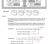
In the below picture (from cp343-2 manual page 41) a 2i/20 module with address 3 has been mentioned as an example.
Bit 0 and 1 from input byte 1 and bit 2 and 3 from output byte 1
have been used. my question is why bit 0 and 1 from output byte 1 has not been used instead of bit 0 and 1?
I mean that i can use for example i300.0 and i300.1 as input
and q 300.0 and q300.1 as output. Am i right?
best regards.

Last edited:


