Help with Connecting over Ethernet to 1769-L24E

Frank Miller

Member
Join Date
Apr 2012
Location
Rush, NY
Posts
6
I am new to PLC programming, and have most of my experience in offline edits. I am trying to connect to the L24 through an Ethernet switch. I have the IP's of all devices on the network and can ping them fine.

When I open Studio 5000 it cannot go online with the controller, and the path shown in Who Active does not display a yellow "question mark" nor red "X" for the controller. It unfortunately does not for any of the devices I have connected to recently...

Can anyone help with this seemingly very simple problem? I have access to all of the information you would need to solve it, I am just having trouble using it...

Thank you in advanced!
 
Not sure you have the correct part number... is it a L32e ? or 23e ?

What does RSLinx show?
 
Thanks GIT.

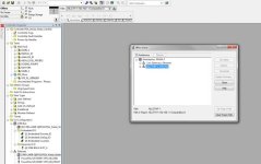
Attached is the screen shot of Studio 5000. It has the processor listed.

I believe I am at a cross roads to the point where I need to learn more about the ETH and ETHIP settings/paths/whatever they are. The path to the controller that RSLinx see's is not the path that is displayed or available.

If you are able to offer any more advice I would appreciate it, again all I'm doing is trying to go online to view active status'

WW Screenshot.jpg
 
The first step I would take is to troubleshoot the basic connectivity between your computer and the network.

PING is a decent first step.

Also try opening the diagnostic web pages for your controllers in a Web browser. All A-B controllers have a diagnostic web page.

Next, examine the settings for your EtherNet/IP or Ethernet Devices drivers in RSLinx Classic. For EtherNet/IP, make sure it's using the right Ethernet adapter on your computer (if you have several). For Ethernet Devices, make sure that the IP addresses of your devices are in the Host List.

One of the things that often gets me is that the EtherNet/IP driver can get confused if you are running both wired and wireless Ethernet at the same time. Shut down all but the Ethernet adapter that's actually connected to the automation network.
 
Hi Frank,
I am a nube to Logix5000 also and I am also woking for the first time on a L24ER just like yourself.

I was only connected to my controler through the USB port as I am just playing with it on my bench at the moment.

When I seen your post I went ahead and configured the Ethernet ports just to see if I ran into the same problem as you did.

Mine configured fine and I was able to connect to the controller via Ethernet no problem.

I know this may sound a bit obvious but do you have RSLinx running and do you have the Driver in RSLinx Configured for the controller you are trying to connect to?

BCS

EDIT: Never mind I see Ken popped in while I was typing, (your in good hands)
 
Ok guys, here's a quick update:

I have configured a new AB_ETH-1 driver to talk to my network. Linx was showing me that my project path was ETH, but all I had available was ETHIP. So I added all devices on the network to the ETH driver so they're visible.

NOW I can connect to my PLC and see all of the devices on my network, it also shows the ones I've connected to in the past. So perfect right? Nope, I am using Studio 5000 and the controller was most likely programmed using Logix 5000.

So this inevitably leads to a needed firmware update, or I can download Logix 5000. (See attached file) So I will let sleeping dogs lie for now, and try to get Logix 5000 running to start. If you have any other tech savvy suggestions I am all ears...

Thanks again!!

Cheers
 
If you have to collaborate with or return the project to somebody who is only using v20, you will need to download v20 and run that.

If you are doing this yourself, go ahead and load the firmware into the controller.
 
Hi Frank,

As Ken posted you can just update your firmware or load it on your PC, I would recommend have several versions on your PC as they are not compatible with each other and it looks like you have the older versions at your plant

The cable is you want to hook up the way sparky is doing it is just a A to B USB cable and you can use the virtual driver in RSLinx

Hope it helps
Mark (aka GiT)
 
Ken & Mark,

Thank you for the help you have given me thus far!

As I had mentioned in the first message of this thread I am not the most prolific PLC programmer. 2 weeks ago I ran into issues with connecting, I am in now. I have the correct version (all of them) of RSLogix to go online with my controller, and now I am to the point of updating code.

Are there any good publications you could point me to in regards to updating the rungs, and toggling bits, etc. I want to force outputs and fake inputs to verify functionality. I can also send you updated pictures of what I am doing, but I didn't want to be annoying by asking a million questions. The functionality I am verifying is not critical in any way and nothing bad will result from my actions :)

Thanks guys!
 
The functionality I am verifying is not critical in any way and nothing bad will result from my actions :)

Glad you have at least considered that, it'll save us all the disclaimer ;)

You can only force physical inputs and outputs. To do so, just right click on them (either in the ladder editor or the tag browser) and click force on/force off/remove force. Note that in the top right hand corner of your screen there is also a drop down menu to enable or disable all forces; obviously that will need to be enabled.

If you need to "force" other sections of code, you can just bridge out the required section with a "test bit" and toggle this bit. As long as nothing is writing to this test bit, it will stay on when toggled until you toggle it back off.

Hopefully that gets you started!
 
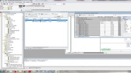
It seems straightforward but for whatever reason I am unable to get my controller to send out that signal. I have attached a screen shot you can take a look at.

I am offline as I write this, but can easily go online with the controller. I am able to toggle the bits necessary to give me my desired function, but for some reason it will not work. My forces are enabled so I would think as soon as I forced the DOUT.6 Value it would light the output light on the controllers embedded IO.

Anything I could be missing? Like unchecked boxes, etc. I remembered the enabling forces after 10 mins of looking around so thank you ASF, did you mean top left?

ScreenShot.jpg
 
Continuing Updates:

I resolved my issue with the force commands. I am unsure why, but after I posted I went back out to trouble shoot and it worked. Go figure.

Now I am to the point where I know my electrical hookups are valid, and my devices are working so I need to check out the code.

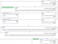
I am reading an input from a flow meter and computing that to correspond to a dosing amount needed for our particular application. In the screen shot you can see the input from the flow meter and the logic associated with it.

The path is as follows: Local:4:I.Ch4Data to FT1_EFFLUENT_TO_MIX_TANK.Input to FT1_EFFLUENT_TO_MIX_TANK.k to FT1_EFFLUENT_TO_MIX_TANK.Output to WWC.Throughput to P7_ADDITIVE.SYS_Rate.

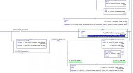
You can see how it is computed in the first screen shot, which brings me to the next one. Here you can see the P7_ADDITIVE being computed and equated. The Dose_Req bit is ideally what I am trying to turn on. (My last post was about forcing this input).

Right now I am going through the code to see if there are any red flags. Probably in a few hours I'll have some more updates, but if someone could answer a quick question: What does the 1.$ mean for the P7_ADDITIVE.P_throughput_trigger_at_value?

Thanks guys!!

Flow Meter Screen Shot.jpg Metering Pump Screen Shot.jpg
 
Frank_Miller said:
I remembered the enabling forces after 10 mins of looking around so thank you ASF, did you mean top left?

Ah but you see I'm in Australia where everything is back to front and upside down... :whistle: glad you managed to find it anyway ;)

The only time I've seen 1.$ come up in a value was when I tried to either divide something by zero, or divide zero by something. Can't remember which way around it was. So off the top of my head I would suggest it means "infinite" or "invalid" result. Check that CPT instruction for something similar.
 

Similar Topics

Hi. I am working on a project where the customer has inquired if it is possible to connect a barcode-reader to the plc to make the setting of...
Replies
2
Views
2,541
Hi, I've never written a program to gather data from a PLC before so I'm very new to this. I've found a lot of information about the DF1 protocol...
Replies
6
Views
7,929
Hello all, hope your week is going well. I am currently working on debugging a Micro850 with Category number 2080-LC50-24QWB. When I connect...
Replies
8
Views
2,347
Hi all Has anyone connected a baumer verisens vision to a tia I have set up the gsd file and have added the verisens to the network On setting...
Replies
4
Views
3,072
Dear all, In a previous post I asked if someone had the software for an old Taian TP02. We used to sell our bandsaw machines with these PLCs a...
Replies
7
Views
2,770
Back
Top Bottom