Interfacing dc motor with s7-200

BHEKI

Member
Join Date
Nov 2014
Location
Eastern Cape
Posts
10
Im working on a small school project and im using a PLC SIEMENS S7-200 which will drive two DC motors but I dnt knw which motors to have. The one I have are 12VDC motors with two terminals but im not sure if they are suited to be interfaced with a PLC, or do I need a special DC motors for my PLC? Since im also new to electronics and PLCs I also dnt knw I how I can connect the motors.
 
What are you trying to do with the motors? Start and stop them or do PWM?
What type of PLC do you have?
 
What are you trying to do with the motors? Start and stop them or do PWM?
What type of PLC do you have?

The motors are driving a boom gate that is they are suppose to go forward and reverse.
The type of PLC is
SIEMENS S7-200
CPU222
DI 8*24VDC
D0 6*RELAY,2A
 
If your motors have a full-load amperage rating of 2 Amps or less, then you should be able to run them using 4 digital relay outputs for each motor (2 Forward and 2 Reverse Outputs for each motor). (Option: use 1 Fwd and 1 Rev. Output, each controlling an external relay that has 2 NO contacts.

It seems that if you have one boom gate, you only need 1 DC motor, with Forward and Reverse outputs to reverse the direction of the DC 12 volt power.

You should use a separate exteranal 12 volt DC power supply to provide power to the motors. Switch this power On/Off using digital outputs of the Siemens S7-200 PLC. Do not use the 24 VDC PLC power to run the motors.
 
Last edited:
So just start/stop right and start/stop left. right?

Than you need to make something like this:
image.axd
.

Make a state diagram, and add everything you can think of regarding a boom gate:
When open from entrance
When open from exit
When close
Emergency
Timers
...

We will help you achieve this, but since this is a school project, do not expect a "turn-key-solution" we want you to learn :).
 
so just start/stop right and start/stop left. Right?

Than you need to make something like this:
image.axd
.

Make a state diagram, and add everything you can think of regarding a boom gate:
When open from entrance
when open from exit
when close
emergency
timers
...

We will help you achieve this, but since this is a school project, do not expect a "turn-key-solution" we want you to learn :).

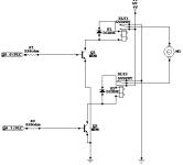
thanks for the reply and information,so this is how i built the circuit but it didnt work at all when i connected it to the output of my plc. MY OUTPUTS FROM PLC ARE 24VDC

CIRCUIT.png
 
Note that this 2-relay approach will give you an abrupt stop, since the armature is being shorted out (dynamic braking) when the relays are both de-energized. This is acceptable in a holding condition, but may not be acceptable either electrically or mechanically in the application.

4 relays would allow for a coast-to-stop situation, and if desired, a time-out, then a shorting state at stop.

According to my program the 1st output(Q0.0) will be high and output(Q0.1) be low as to run the motor forward, both be low as to stop the motor and lastly Q0.0(LOW) and Q0.1(HIGH) as to reverse the motor. But my main problem is that when I connected the circuit to my PLC the relays do not even close as to run the motor. So I thought maybe my connection is wrong. When I tested the circuit with power supply it was working but when I interfaced it with my PLC it not working at all
 
The way your circuit is drawn, the relay coils have no power. Normally you would not need the transistors. The PLC should supply voltage from Output terminals directly to the relay coils.
...I have also supplied 5V to the collector and across one side of the relay coil.
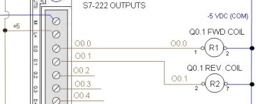
I assume that was an effort to reduce a too-high supply voltage down to 5 volts, or what?? Are the relay coils rated for 5 volts? If so, all you need to do is connect the +5 volts to your 1L Common terminal, then from the Q0.0 and Q0.1 output terminals to one side of each relay coil, then from the other side of each coil to -5 volts. Forget the transistors.

When I tested the circuit with power supply it was working but when I interfaced it with my PLC it not working at all
What voltage did you supply to the 1L and 2L Common terminals for your relay outputs? (I am betting on 0 or nothing)!

PS: At 5 volts, your 12 VDC motors will run at 5/12 of full speed, or at 42%.
 
Last edited:
Are you certain that both relays are not energized? The leakage current from the PLC could be actuating both relays in which case the motor will not run.
 
I think this S7-200 has relay outputs, so there would be not leakage current. However each Output relay contact common (IL and 2L in this case) has to be connected to some voltage source.

SIEMENS S7-200
CPU222
DI 8*24VDC
D0 6*RELAY,2A

MY OUTPUTS FROM PLC ARE 24VDC
Sorry, but your outputs are relay contacts, so they will have no voltage unless you connect something to the "1L" common terminal. If you connect +24 VDC, I don't see how that will cause the transistors to switch. Unless the transistors switch, your relays will not operate.

Interfacting DC Motor- Bheki.jpg
 
Last edited:
I think this S7-200 has relay outputs, so there would be not leakage current. However each Output relay contact common (IL and 2L in this case) has to be connected to some voltage source.

SIEMENS S7-200
CPU222
DI 8*24VDC
D0 6*RELAY,2A


Sorry, but your outputs are relay contacts, so they will have no voltage unless you connect something to the "1L" common terminal. If you connect +24 VDC, I don't see how that will cause the transistors to switch. Unless the transistors switch, your relays will not operate.

there is 24VDC connected to 1L and 2L, must I remove the transistors?
 
there is 24VDC connected to 1L and 2L, must I remove the transistors?
If your relay coils are rated for 24 volts DC, then you do not need the switching transistors. 24 volts applied directly to the external relay coils will cause the relays to switch their contacts. If you are using the transistors to switch 5 VDC to the relay coils, then your Base voltage must be 0 or grounded when the transistors are OFF, and full Vcc voltage when they are ON.

If your relays are rated for 5 volts DC, then you must make sure that that is all that is applied to the coils. To use NPN transistors as switches, I think the Base-to-Emitter voltage has to be greater than about 0.7. You must end up with +5 one one coil leg, and -5 on the other coil leg. Here are the requirements to set up a NPN transistor to conduct as a switch:

• The input and Base are connected to Vcc
• Base-Emitter voltage VBE > 0.7v
• Base-Emitter junction is forward biased
• Base-Collector junction is forward biased
• Transistor is “fully-ON” ( saturation region )
• Max Collector current flows ( IC = Vcc/RL )

• VCE = 0 ( ideal saturation )• VOUT = VCE = ”0″
• Transistor operates as a “closed switch”

In your case, I think that Vcc should be about 5 volts DC, not 24 volts DC.
For a 24 volt Vcc, and ASSUMING that your relays need about 2 Amps to energize and your transisitors have a typical Beta of 200, then:
Current through Base = IB = Ic/B = 2/200 = 0.01 Amps
Resistor at Base = (Vcc-0.7)/IB = 23.3/0.01 = 2330 Ohms = 2.33 kOhms, not 330 Ohms.
 
Last edited:

Similar Topics

I have a Cognex Insight 2000-130 camera that I'm trying to get talking to my PLC. Both are connected to the same router via Ethernet. Thus far...
Replies
12
Views
1,193
Hi, I am picking up a project started by a predecessor who is now out of contact. It is a Siemens S7-1515F PLC system - but the query is how you...
Replies
2
Views
713
Hi everyone, I've got to interface 4 x Mitsubishi Q series PLC's with an Allen Bradley Compact Logix PLC using a Red Lion Data Station DSPLE000...
Replies
1
Views
500
hello i want to read temperature data from Masibus UT94 temperature transmitter which is giving data on RS485 port. i have assigned ID:-30 and...
Replies
1
Views
1,049
Hello I am very familiar with ladder logic and PLC programming, however I am new to Allen Bradley, ethernetIP, and interfacing measurement...
Replies
3
Views
1,007
Back
Top Bottom