Create a flip-flop control?

Davek0974

Member
Join Date
Nov 2014
Location
Hertfordshire, England
Posts
145
Could someone suggest a bit of code that would create a flip-flop control for a pneumatic cutter system please, couldn't find much in search so maybe its not called that?

I have the following...

cutter air valve,
cutter sensor - home,
cutter sensor - out,

the cutter works both ways - home direction and out direction so to save time and wear it parks at the out position as well as the home position while running non-stop.

I have tried a couple of ideas but once triggered they seem to get stuck in a loop.


many thanks
 
Brilliant, sure there is something in there, not sure if they are all cyclic or not yet but i need a one-shot style - an OSR triggers the knife to move out and the same OSR triggers it to come home.
Yes, those 10 methods are all "cyclic". The trigger bit (I:1/0 in the program) causes the Output to go ON the first time, then OFF the second time the trigger bit goes ON.

Since that file was made, I am now up to 13 different collected Alternator methods (see attached for a better PDF copy). I might could help you set up the alternator (flip-flop, toggle) logic if you say what PLC you are using. This method can be adapted to control 2 different Outputs, alternating between the 2 each time the trigger bit goes ON. Method #11 is one version of controlling 2 Output bits with one Input trigger.

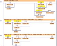
The attached picture is an example of using Method 1 to allow one input (Stop Float Switch) to alternate between 2 Pumps.

Alternating Pump Sewer Lift Control- Dronai RELAYS.jpg
 

Attachments

  • ALTERNATOR METHODS.pdf
    84.6 KB · Views: 79
Last edited:
Are you sure that a One-shot will provide a pulse long enough to trigger the cutter air valve? If so, then it seems that this is not a true alternator or flip-flop, but rather a case of 2 sensors (Cutter Out, Cutter Home) doing 1 thing (activating Cutter Valve).

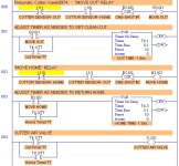
Something like the attached picture might be close. This logic produces a pulse of 1 PLC scan duration, each time the cutter arrives at OUT or HOME. If the pulse needs to be longer than 1 scan, then the logic will need some additions (timers as Osmanmom said earlier).

Pneumatic Cutter- Davek0974.jpg
 
Last edited:
I think we need more details as to what the sensors do and/or where they're mounted. I'm guessing the sensors are position sensors to detect when the cylinder is fully out and fully home. I'm also guessing that the cutter is connected to a single-acting valve. IOW, ON = Go Out; OFF = Go Home

Your logic would work if he had a double-acting valve, with each .TT bit firing the appropriate solenoid. With a single solenoid, I think it would fire out and just remain there.

My best guess is that there is a separate 'GO' signal, and the position sensors simply let you know where the cylinder is. In that case, standard flip-flop logic should work, with the 'GO' signal as the initiating one-shot.

Personally, I would use a 2-position, double-acting valve and skip the flip-flop. Each time the 'GO' signal transitions from OFF to ON, look at which position sensor is ON (and verify that the other one is OFF), then fire the appropriate solenoid until the sensor turns OFF. This guarantees that the output is on long enough for the valve to actuate. The valve spool will remain in the last position, so the cylinder will finish its stroke.

But that's just me ;)

🍻

-Eric
 
Thanks for the code, i should have given full details, apologies.

The machine is a web-fed label stamping press, the knife is fitted to a linear slide which has a sensor at each end, this slide is connected to a single solenoid valve, I think the designation is a 5/2 valve.

At the end of each stroke of the press, the web is advanced and the cutter activated for either an outward or a return stroke but not both - it sits at either end between cuts.

I think I have found the logic now, thanks to this thread, that will enable the state of the solenoid to be switched and held either way from one input, it's only two rungs and no latching bits ;)


Dave
 
Dave, I would be interested to see your solution, if you could post a JPG picture or PDF of the logic.
 

Similar Topics

Hello, I've been trying to learn this a while now and still have not found out how this works. I have an Omron CJ2M PLC and an ABB ACS 355 VFD...
Replies
1
Views
243
Hello, I have to deal with iFix again and am looking at the most efficient way to create alarms to display in iFix, i.e. not creating an...
Replies
0
Views
155
Good morning to all, I have the following issue, I installed everything of intouch including the patch, it is the 2023 version. The...
Replies
0
Views
330
So, I finally got versioin 27 installed on my Windows 10 VM. However, now I can't upload a project from my lab controller. I have the above error...
Replies
0
Views
1,129
Hi all, I have few GB of logged data created by RS View 32 Works, it is all in .DBF format. At the moment, my company wants to shift all data to...
Replies
14
Views
1,451
Back
Top Bottom