Question about using the ALARMS SETUP in Factory Talk View Studio

ksa858

Member
Join Date
Jul 2014
Location
Danville
Posts
84
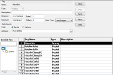
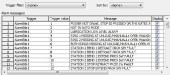
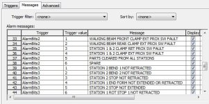
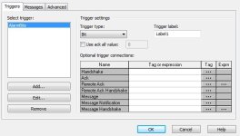
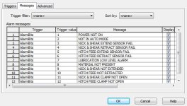
I have a project that use to have a Panelview 600 but is now being replaced with a Panelview Plus 700. It communicates with a CompactLogix L35E. I imported the Panelview 600 project to the PanelView Plus 700. The question I have is if the information that was imported for the alarm setup in the PanelView 700 is accurate. I have attached the settings that were imported on the alarm setup screens and tags screen. It looks like B3[8] is used as a word for the alarms. Is this accurate or is there another way I should be doing this in the Panelview Plus?
triggers.JPG messages.JPG AlarmBitstags.JPG
 
I can't say if it is correctly setup since I am not familiar with your process, but it does look right.

It would appear that you had a SLC 500 or PLC-5 controller that was converted to a Logix 5000 controller. The older PLC/SLC system used B3:8 for triggering alarms where the new system is using an array named B3 and element number 8 which works out to be B3[8]. That is identified in FT View as "AlarmBits".

That location contains bits 0-15 in the PLC/SLC system. In the 5000 that may still be 0-15 or it could be 0-31. But that likely does not matter here. Each bit triggers a specific alarm and its corresponding message.

There is a gotcha here that existed in the old system and still exists in the new system that can be really confusing. On the MESSAGES tab, the Trigger value specifies which bit triggers which alarm. So, it isn't a "value" so much as a bit number. The gotcha is that a trigger cannot be "0".

So in your PLC/SLC/5000 the bits are numbered as 0-15, but the trigger values would be 1-16. So bit "0" (B3[8].0) in the PLC is trigger value "1" in the Alarm setup. The last bit "15" (B3[8].15) would be trigger value "16".

Anytime any of those bits are equal to a value of "1" it will trigger that specific alarm.

OG
 
So if I had an occasion where multiple arrays, such as B3[8],B3[9],
B3[10], or B3[11] were used to trigger alarms, could I assign the triggers as AlarmBits1, AlarmBits2, AlarmBits3, and AlarmBits4 in the Trigger box under alarm messages?
 
Yes, you are correct.

1. Create your tags.
2. Create your Triggers using new tags.
3. Create your Message and select Trigger and Bit
 

Similar Topics

Hi all, I'm working on a safety circuit and had some question about fusing. Incoming supply - 120V/15A Power supply - PSL-24-060...
Replies
5
Views
574
I know this can be done, but I can't get the router config right. My goal is to physically connect(using an ethernet cable) a device(PLC, RTU...
Replies
9
Views
1,016
I'm a novice with Rockwell s/w and a rookie working with virtual machines. I needed a way to support multiple FTView ME versions. so I set up a...
Replies
5
Views
2,960
I am looking to fuse only the commons of my IO cards to protect the plc. Each input point is rated at 6.5 mA with a total of four points, in...
Replies
2
Views
2,751
I operate a distillation column for Argon gas. It has a pressure controlling valve that cools a condenser at the top of the column with nitrogen...
Replies
4
Views
2,272
Back
Top Bottom