Automation Direct DL-05 w/ Incremental Encoder

Freebird01

Member
Join Date
Dec 2014
Location
indiana
Posts
34
Ok first off this forum is great! tons of info...

I am a 3d CAD guy/machine designer by trade. I have been working on designing industrial machines for the better part of 10 years and know a little about plc's and their components to be dangerous. I have always been fascinated by the programming end of things and recently decided to take the plunge and trying to learn this.

The Automation direct stuff was had cheaply on ebay as well a some other components. As a primer into this world, I built a controller to piggy back on a manual style tubing bender. I will be converting it to a hydraulic ram with a solenoid valve to control up and down motion. I purchased a 360ppr incremental encoder from ebay (chinese but hey it should work fine for now).

The idea is i want to be able to tell the plc what angle i want to bend to...let it cycle the cylinder and use an encoder to tell it where to stop and start. I will have limit switches for homing the encoder and im running a EZ-text panel for manual inputs.

I am figuring out the inputs/outputs well enough but what has be baffled right now is getting the plc to recognize the encoder and just give me live playback to my lcd panel. as in i turn the encoder shaft by hand and have it display the angle on the LCD and be able to hit a button for reset.

i tried inputing the logic thats on this website directly and im getting nothing...

http://quantumdevices.wordpress.com/2010/04/19/optical-encoder-pulse-counting-with-a-plc/

What am I missing??? I know i have to output to a bit so the lcd panel can retrieve it and display it...please forgive me if this seems like a dumb question... my head is still spinning lol. any help would be appreciated. 🍻
 
I'm not that familiar with the DL-0x series but I did note this: Note that CT174 was not picked arbitrarily, it is the specified counter location for high speed counting.

The link you referred to uses a DL-06 and you are using a DL-05. From the DL-05 manual: Using CT76 and CT77, the quadrature
counter can count at up to a 5 kHz rate.


You also need to set the counter mode correctly and there may be other differences between the two processors.

I'm sure someone more knowledgeable will be along shortly.
 
I'm assuming you wired the encoder's channel A and channel B signals to PLC inputs X0 and X1. I'm also assuming that you have a 24 VDC encoder and DL-05 with 24 VDC inputs. Are the X0 and X1 inputs never changing state? If so, you have a wiring problem. What type of encoder did you buy? Post or provide a link to its wiring data sheet.

Depending on the speed of the encoder you may need to use the high speed counter functionality, but we can deal with that after you've worked out the wiring issues.
 
My apologies... I should have known to provide this info.

I purchased this encoder..

http://www.ebay.com/itm/NEW-Increme...653?pt=LH_DefaultDomain_0&hash=item43b3c60bd5

I had to do some google translate to figure out the wire colors but i have this

red: V+
black: ground
Yellow: Channel "A" (run to X0 on PLC)
Blue: Channel "B" (run to X1 on PLC)

My PLC is a AD D0-05DD-D. running on a 24vdc power supply.

I have C0 on the PLC running to the Vdc+. Both status indicator LED's on the plc are lit up with all this connected.

There is no concern for speed in this application. the encoder will never move at more then 3-5rpm and will never make a full rotation. 120Âş will most likely be the most it will ever see. it will move from 0Âş to say 90Âş then back again 99% of the time. right now with trying to learn the ladder logic and understand the elements i am just trying to have the plc direct read the encoder while i spin the shaft by hand just like in the video in the first link i posted.

*edit* Doug, I had appendix E of the DL-05 manual here printed out while im writing the code. I caught that with the CTxxx numbering and numbered my counter CT76 as in the instructions. I messed around with the different mode settings (i.e. 10,20,30,40,50) and assigned the proper values to the V-memory locations' as per the appendix E, using the Memory Editor. If i am reading the appendix right, on page E-22, the first line of boxes tied to SP0 are doing just that...loading those values into the proper V-memory locations.

hope that helps clarify!
 
Last edited:
Note that as you turn the encoder very slowly you should see X0, X0+X1, X1, neither. Either in the order I wrote them or in the opposite order depending on which way you turn the encoder. If you don't get that you have something wired wrong.
 
AutomationDirect PLC DL-05 Encoder Input

Good Afternoon,

If you are not seeing the led's for X0 & X1 on the plc changing states this could be a wiring problem or a bad encoder or bad inputs on the plc. Check with a DMM.
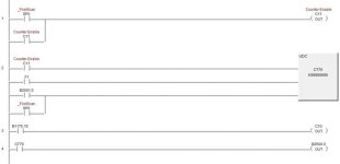
Can you post your program?

Tom
 
I have a Digital Meter here in front of me.

On the program I have changed X1 and X0 with no change in results.

If i hold the black lead to ground and put my red(+) lead on x1 and spin the encoder I will get a voltage change from 0v to 9v then to 18v and back again...

If i hold the black lead to ground and put my red(+) lead on x0 and spin the encoder the voltage will almost stay constant at 4.5v and will change slightly as i rotate it from 4.5v to 4.8v


BTW rung 5 is (end)...its just cut off the pic

*EDIT*
B2501.0 is the "F1" key on my EZ-text panel
I have B2500.00 setup as the variable the LCD panel reads from the PLC to display the angle.

prgm.jpg
 
Last edited:
Freebird01

First in your ladder logic where are you enabling counters CT76 & CT77 as a High Speed counter HSIO 20?

Check wiring from encoder to X0, this voltage is below the minimum voltage to trigger X0.

FYI for larger programs, using DirectSoft 5 you can export your project by

File > Export > Program... do the same for rung description and elements.
This will save them in a note pad. To view a project in note pad just reverse.

Tom
 
I manually edited those with the "memory editor" utility in DS5. Must I also do that in the program itself?

I am thinking i got a fried encoder... the wiring connections are tight and look to be in the right locations to me...
 
If i hold the black lead to ground and put my red(+) lead on x1 and spin the encoder I will get a voltage change from 0v to 9v then to 18v and back again...

If i hold the black lead to ground and put my red(+) lead on x0 and spin the encoder the voltage will almost stay constant at 4.5v and will change slightly as i rotate it from 4.5v to 4.8v

It is difficult to tell from your post, exactly what points you are taking the measurements from.

We need to test the voltage between C0 and X0 on the PLC as you are rotating the encoder. Then We need to test the voltage between C0 and X1 on the PLC as you are rotating the encoder.
 
yes thats from C0 to X1 and X0 respectively....

just cut my encoder wire right before my quick disconnect fitting and wired direct to the plc...

yellow to x0
blue to x1
red to c0
black to ground

now im seeing X1 flash on the PLC...but i get nothing from x0 guess its possible i had a hair of a wire touching inside my connector and fried channel A of the encoder...
 
Last edited:
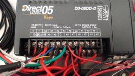
I know the wiring is a tad messy but keep in mind this is a personal project to learn the terminals are a tad small for spade connectors.

C0,C1, and C2 are connected to VDC+ on the power supply
the black shielded wire on the left is from the encoder

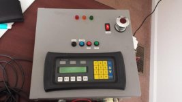
the other inputs are mechanical push buttons on the front of the panel and 2 mechanical limit switches. the outputs currently are just 3 LED lights on the front of the panel.

20150111_140854.jpg 20150111_141547.jpg
 
On page E-3 in the manual it shows (+) of encoder to +24 of the power supply. It also shows the encoder ground and C0 on the plc connected to the (-) of the power supply.

Based on your posts it appears that you have C0 connected to the + of the power supply not to the - of the power supply.
 
Last edited:

Similar Topics

Hello, I have an automation direct d2 262 plc and C-more HMI EA9T6CL-R. I need to prepare a program, scheduled to be performed on a future date. I...
Replies
1
Views
119
Hello all- I have a unique challenge using a customers Direct logic 06 PLC. This customer has a DC motor operating at 10 RPM which is turning a...
Replies
1
Views
136
Hi, I have been trying to run drive via Sysmac studio. I can ping the drive. I can see the logic bits going on/off as per command. But, drive is...
Replies
21
Views
563
Anyone tried Automation Directs new CM5 HMI. We've been the EA9's for a few years now with minimal complaints. A few failures here and there but...
Replies
17
Views
1,584
I'm using an Automation Direct GS20 VFD for the first time and I have a question for the Automation Direct gurus regarding the recommendation of a...
Replies
2
Views
1,095
Back
Top Bottom