Question about shielding and grounding signal cables

mikas_m

Member
Join Date
Feb 2007
Location
ck
Posts
154
Hello to all,

i'm reading the manual regarding this module from Siemens, and since English is not my native language I'm not sure if I understand this text correctly:

Clamping the cable shielding
The shielding of cables carrying analog signals and of PROFIBUS DP cables
should be clamped and grounded upstream of
the terminals on the module. If the
cables are not grounded until further downstream at the strain relief, any high-
energy interference from the shielding will be discharged across the module
enclosure, and thus impair the module’s resistance to interference.

I wonder how to process correctly. I use copper solid wire cable like this one. This cable has alu foil and drain wire that needs to be grounded on only one side of the cable.

Now since the analog input and output signals will be transmitted via this cable, I wonder should I ground this drain wire on the module side or on the other side of the cable (in local junction box)?
Not really sure what this "upstream" and "downstream" means.
Normally in my previous experience cables with analog signals from the field were grounded in the PLC cabinet very near the PLC input card.

Can you please help me understand this part of the manual? If I understood this correctly, I need to ground this drain wire near the connector terminals on the module and not to go further (outside) the module.

Thank you
 
Last edited:
Think of it like a river or stream. Put a rock i the middle of the stream. Upstream is above it coming towards it, downstream is below it, heading away from it.


Ground it at the sending device is what they are saying I believe. This way interfering energy is negated as best as possible before it hits the receiver.
 
We ground and shield on our cabinet end, where the cable enters the cabinet. The remaining distance to the PLC is regular wire, not cable.

I think it is a little bit of taste as well, people seem to disagree. Also check if you have to supply according to a certain standard.

For example, the following is from the NORSOK standard:

http://eelife-lixin.blogspot.com/2014/05/instrumentation-earthing-system.html
 
Ah, germans germans germans. They have a tendency to write in a way that you have to know a lot of things that are assumed.

further downstream at the strain relief
The "strain relief" is probably a copper earth bar at the bottom of the control cabinet. It doubles as strain relief (*) and shield termination. The mantle of the cable is removed in a 2 cm section, so that the screen is exposed and you can place a clamp over the screen onto the copper bar/strain relief.
This is the "proper" way to do it anyway IMO.

The mantle on the shielded cable should not be removed (apart at the clamping onto the copper bar), but be kept on the cable as far up in the control cabinet as is practically possible. In this way the the length of un-screened wires is minimized.

*: Many control cabinets do not have cable glands, but merely a rubber or foam gasket to keep dust out. Because of that there must be some other way to fasten the cables in the control cabinet.
 
Last edited:
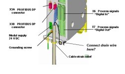
Thank you all for the answers, but I'm not still 100% sure, Jesper, the strain relief is marked in the pic of the module. Please have a look in the attachment.

So If I understood OK, the drain wire should be connected to the screw on the closer?

Module.jpg
 
According to the text you quoted in post #1, yes the shield should be connected here.
And you should definitely connect the shield by clamping, NOT by connecting the thin "drain wire" to an earth screw.

edit:
This text from the quote
If the cables are not grounded until further downstream at the strain relief, any high-energy interference from the shielding will be discharged across the module enclosure, and thus impair the module’s resistance to interference
tells us that the screen should ALSO be clamped to the main earth busbar / strain relief.

I have read and heard many opinions about shield connections. One opinion is that ground loops should be avoided. The recommendations by Siemens for that module seems to indicate that to drain "high energy" interference at the main busbar is more important than avoiding ground loops.
 
Last edited:
Hi Jesper,

the confusing part is that both text and the pictures are from the same manual. So at first I thought that strain relief is also an earth bar in the cabinet, but i n the pic it is on the module itself.
I have a signal cable with 8 wires 4x2 (four twisted pairs) and it has alu foil + drain wire.
In most other applications, this drain wire was connected to the earth bar at the input of control cabinet and from that there were wires to input PLC card.

The confusing part for me for this particular module is this pic and text I quoted.

Thank you
 

Similar Topics

Hello again..trying something on an existing poorly written program and just wanted to double check something system is an A-B MicroLogix 1200 In...
Replies
5
Views
165
Good morning! Let me start by saying, I am still learning about this type of HMI programming. I recently watched a video about recipes and how it...
Replies
0
Views
68
I have some logic that I have written within a 5380 series controller that tracks the time an event is started, while the event is running an RTO...
Replies
2
Views
91
I have an HMI 2711R - T4T Series B, and I want to know which PLCs, besides Micro 820, can communicate with it.
Replies
2
Views
80
HI i would like to know how to get a variable that will store the amount of times a program has been executed. The issue is I have 3 DBs for 1 FB...
Replies
2
Views
79
Back
Top Bottom