Seems to be a simple programming question

Join Date
Feb 2015
Location
North Carolina
Posts
3
This is for a class project. Seems to be simple, but I feel I may be overthinking it.

My conveyor motor is controlled by two outputs.

O:0/2 turns the motor in the forward direction.

O:0/1 (relay) and O:0/2 turn the motor on in the revere direction.

Say I wanted to do this...

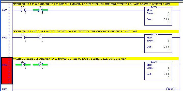
I:0/1 turns on O:0/2

I:0/2 turns on O:0/2 and O:0/1

How would this be written in Logix500 so that I can change directions?

Thanks for any and all help!!
 
Last edited:
Welcome to the forum.

You have O:0/2 listed in your description as forward and reverse.

May I suggest the following.
1. Write down what you want to do. Review and edit if necessary.
2. Add I/o to your document.
3. Do the plc program, zip it, and attach to the forum.

we will be more than happy to look at your work and suggest any changes.

regards,
james
 
That is correct.

O:0/2 runs the motor in the "forward" direction.

When O:0/2 AND O:0/1 (relay that reverses the polarity) are on, the motor runs in the "reverse" direction.

Unfortunetly, it must be wired this way.

The inputs used in my example are at random, just to help explain changing direction based on conditions.

Looks like jawolthius's logic would get the job done. I was thinking I would have to use a bit (B3:..) somehow.
 
Last edited:
Make sure that a change in direction does not happen too quickly. The motor needs to come to a halt before applying power for the other direction.

In applications I made sure enough time had passed before changing the reversing relay, either on or off. The run (O:0/2) would probably be capable of absorbing the turn off spike from the motor. The reversing (O:0/1) should only be changed when the motor is fully stopped.

Of course a very small motor, like for a small classroom tabletop project may not need that level of protection.
I've written an example program in LogixPro based on your description. I will post it later but will wait for the OP to post their attempt first as James McQuade has requested.
 
Last edited:
So my example uses inputs 1 and 2 and outputs 0 and 1. The principles are the same regardless of which inputs and outputs are used. What I like to do when working on something relatively simple is first break it down to binary (where applicable) and work from there. The inputs and outputs are really reflections of bits with each input represented by one bit in a word and each output the same. In this case all you need to do is take what is needed via the outputs, come up with the binary number (I.E. 0 1 0 = output 0 off, output 1 on, output 2 off), translate that to the decimal number and move that to the outputs when certain conditions are met (I.E. when input 1 and 2 are on send “3” to the outputs turning on outputs 0 and 1).

EXAMPLEcopy_zpsf604f460.jpg


The only problem with this method is that the maintenance people will hate you for using it. Why use moves and math when simple outputs will get it done and be easier to decipher?
 
I'd also add a slight start dwell to O:0/2 so that there is no way for the motor to plug.
 
Here is a bit more refined version than the one I posted in post #10, see attached.
 

Similar Topics

Hey, I have a micrologix 1000 with RSLogix 500 Pro software. in a small program I have 3 inputs and I watch them change on the data table but the...
Replies
9
Views
2,047
Good Evening , I have an " Oddball " Blower Motor , and really do not have any U.S. support . It is a manufacture called EBM Papst and the...
Replies
4
Views
1,143
I'm one to grab hold of a gift horse's mouth, shine a torch down it's throat and have a bloody good look... I've only really used A-B...
Replies
8
Views
3,457
Hey guys, I'm seeing some odd behavior with some MSG instructions I have set up. Specifically, when I enable the MSG instruction I nearly...
Replies
5
Views
6,015
Hi all, so I discovered a feature I did not know on a logix platform. Hot plugging of modules. I tested it the other day on a V19 system...
Replies
7
Views
6,725
Back
Top Bottom