3 way contiuous

dpforum

Member
Join Date
Feb 2015
Location
Vincennes,In
Posts
21
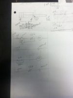
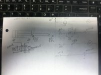
Hi, my name is Danny & Im currently a student of relay logic. Just a beginner. I am on here to learn everything I can about ladder logic. I have attached a file of one of the problems i am currently working on. I am hoping someone has the time & does not mind checking my work. Im open to corrective criticism & or tips of a better way.

written version of problem:
double acting cylinder, 3 position, 4 way, double solenoid valve; continuous operation.
Ladder diagram: start/stop rung, 2 relays, 2 limit switches & 1 e-stop.
the cylinder rod will stay in position when the e-stop is pushed.

Please & thank you.
regards dp
3way continuous.jpg
 
What happens when the cylinder is between the limit switches?... looks like everything will stop, how about adding a latch to CR2 ? you have CR1 latched but not CR2

Also are the limit switch correct? should it be a held open and not just a N/O ?
 
also- if you start retracted, and then hit the extended switch limit, you will not retract again because CR1 never shuts off. CR2 can't energize untill CR1 is off.
 
Hi, my name is Danny & Im currently a student of relay logic. Just a beginner. I am on here to learn everything I can about ladder logic. I have attached a file of one of the problems i am currently working on. I am hoping someone has the time & does not mind checking my work. Im open to corrective criticism & or tips of a better way.

written version of problem:
double acting cylinder, 3 position, 4 way, double solenoid valve; continuous operation.
Ladder diagram: start/stop rung, 2 relays, 2 limit switches & 1 e-stop.
the cylinder rod will stay in position when the e-stop is pushed.

Please & thank you.
regards dp
After reviewing I can see that my logic is wrong:(
 
the problem did not call for a latch, but it is possible that it should have been written in too.
thank you

You will find this time and time again... your boss is going to tell you what they want done and they will leave out a lot of the details, it going to be up to you to figure out the issues and what is needed to get the job done

Welcome to the wonderful world of automation, glad to see someone trying to figure out the problem like you did, most dont give it half the effort 🍻
 
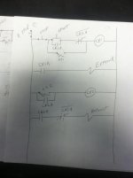
this is my revised version of the ladder logic. Please view & give feedback
regards dp

I attached another copy of ladder logic that is ia bit more clear.
the only problem with this that i can see is that Ls1 can be instead of start button if cylinder is fully retracted.
please give feedback
regards dp

revised 3way.jpg more clear 3 way.jpg
 
Last edited:
Nice- your very close! I think there's one more issue.

CR2 never unlatches after it's made. What will happen is when the cylinder retracts and goes to extend again, it will only extend as long as LS1 is made and then stop. Then it will be stuck in a loop of short stroking. This is because CR2 never unlatched.
It's only after CR2 is turned on and latched that this will happen. I'm sure you'll figure out the fix :)
 
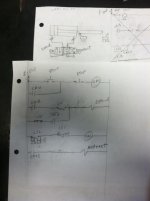
Hallelujah! I believe i have finally got the write sequence of events in my ladder logic. Thanks to everyone who has responded to my tread. Please check out my revised/revised/revised etc version of ladder logic. Keep in mind this is assuming that the cylinder is fully retracted & LS1 is made when start button is pushed.

thanks regards
dp

final revision 3 way.jpg
 
Think you have a winner! In real life, you would have to have all those limit switches adjusted just right. If not your cylinder might stop if the switches didn't "overlap" so to speak. Nice job of making the corrections! :)
 
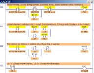
Following up, your ladder diagram (not the electrical schematic diagram of your physical equipment which is different) should be redrawn something like the attached LogixPro PLC Simulator file, which tested to work correctly and meets all your stated requirements. Notice that because of the way the PLC operates, you need about 3 contacts from your E-Stop switch to halt everything when the E-Stop is activated.

Notice that the E-Stop and the Stop PB instruction (although the physical switches on your wiring diagram are Normally Closed) needs to be the XIC (Examine If Closed) instructions as shown.

Double-Acting Cylinder Control- DPForum.jpg
 
Last edited:
Back
Top Bottom