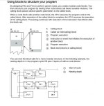
Siemens scan sequence

ASF

Lifetime Supporting Member
Join Date
Jun 2012
Location
Australia
Posts
3,921
Hi all,

I primarily use AB PLC's, and have a reasonable understanding of the way they scan their logic. I've done a few smaller projects on Siemens, but have now come up against a larger one, and think it's probably about time I fill in a few gaps in my understanding so I go about things the right way :)

1. In an AB PLC, a routine is not scanned unless called by a JSR (jump to subroutine) instruction (except the main routine, of course). As far as I'm aware, there's no such instruction needed in Siemens (because all of my programs up until now have worked without them!), so how does the PLC determine which order to execute the OB's in?

For example, I created 10 routines and numbered them in the range of OB200 to OB299. Then I realised I'd missed one, so I added it in and numbered it OB250. But it still appears on the list after OB299. So does the PLC scan the OB's in numerical order, or in the order they appear in the project tree? And in either case, is there a way to satisfy my OCD and make OB250 appear halfway up the tree so all of my OB's are in numerical order?

2. Once I establish the order each OB is executed, am I safe in assuming that the rungs are always scanned left to right, and then top to bottom?

3. Do Siemens PLC's in general - and more specifically, the S7-1200 - follow the standard "read inputs>execute code>write outputs" sequence, or do they (it) update the I/O asynchronously a la Control Logix? (ignoring all the possible exceptions to do with interrupt i/o, etc etc)

I appreciate any insight!
 
Hmm. Yes, I have misunderstood! You CAN just put all your code into different OB's, and as long as they're numbered above 200, it will just cycle through them all in numerical order, which is obviously how all my little projects have worked so far! :oops:

So a better approach, then, is to create FC's for all my code segments, and call them in OB1 in the order I desire, am I right?
 
1. In an AB PLC, a routine is not scanned unless called by a JSR (jump to subroutine) instruction (except the main routine, of course). As far as I'm aware, there's no such instruction needed in Siemens (because all of my programs up until now have worked without them!), so how does the PLC determine which order to execute the OB's in?

For example, I created 10 routines and numbered them in the range of OB200 to OB299. Then I realised I'd missed one, so I added it in and numbered it OB250. But it still appears on the list after OB299. So does the PLC scan the OB's in numerical order, or in the order they appear in the project tree? And in either case, is there a way to satisfy my OCD and make OB250 appear halfway up the tree so all of my OB's are in numerical order?

As you already found, the program OB's get executed in number order: 1, 200, 250, 299, etc. However, there are OB's that get called at different times than the main program cycle. The most commonly used are cyclic interrupt OB's, which get called at a specific interval. There are also time of day inturrupts, event inturrupts, and plus some error handling OB's. These all have higher priority than the main program cycle OB's, and will interrupt it, then execute the new OB, then return to exactly where it left off.

2. Once I establish the order each OB is executed, am I safe in assuming that the rungs are always scanned left to right, and then top to bottom?

Yes. Things can get a little tricky on rungs that have multiple branches, but in general, top to bottom and left to right is what happens.

3. Do Siemens PLC's in general - and more specifically, the S7-1200 - follow the standard "read inputs>execute code>write outputs" sequence, or do they (it) update the I/O asynchronously a la Control Logix? (ignoring all the possible exceptions to do with interrupt i/o, etc etc)

Yes, the 1200's follow the standard cyclic read inputs/call program/write outputs. The other Siemens PLC's do as well, but some of them have options that allow you to change how it works a little bit.

4) There is nothing wrong with using multiple OB's to hold each of your subrutines. This isn't the "standard" Siemens way of doing things, because the functionality was new to the 1200's. If it works for you, and makes sense, keep doing it.

However, the FB's and FC's allow you to modularize your code, which can simplify a lot of things and reduce engineering time. Imagine an example where you program a subroutine that does a task, like controlling a section of conveyor. If you wanted the PLC to control an additional section, you would have to copy the OB, make a copy of every tag, and then change all the tags from conveyor 1 to conveyor 2. Instead, if you programmed that as an FB, you can use internal tags that get stored in the instance. All you need to do is link the inputs/outputs of the FB to your real world IO and control signals/sequence. When you add conveyor two, you create a new instance for it, and all the internal tags are already pointing to the right place. All you do is change input/output parameters, and you control a whole new line with minimal work. The best part is that they share the code, so if you realize down the line that you need to make a change to the control code, you can test it on line one, and then the changes automatically affect line 2 as well, with no extra work.

You can do something similar with FC's, the difference is that they don't have an instance that stores their data from cycle to cycle. An FC could be used for making something like an addition block, where the output is only based on the inputs. An FB would be needed to calculate an average, where, in addition to the inputs, it also needs to remember the sum and number of values to be able to calculate the output.

These are more or less analogous to the AOI's in the Rockwell world, but I think are much more commonly used by Siemens programmers than Rockwell ones.
 
I personally use OB35 for most of my program. Most of the FC's have some kind of PID in it, and they like a cyclic OB.

Also, a 100ms cycle time is plenty fast for my applications.
 
Thanks for all the replies, it's starting to make a lot more sense! Yes, I worked out that a Function Block is similar to an AB Add-On Instruction, and I've set about re-writing all my motor and valve control AOI's as FB's.

I'll have a read of those documents and see what other questions I come up with. I think I'm approaching this with the mindset of trying to "translate" all the Siemens features into their equivalent AB features in order to understand them, but the platforms are different enough that there just isn't a straight equivalent in most cases, so maybe I need to change my approach a little. I guess it's kind of like learning another language, and finding out that there's no exact equivalent to an english word in that other language, and you have to use a whole phrase to convey the same meaning. And then you learn a word in that language and find that english has no equivalent and you have to use a whole phrase to translate it back :)
 
OK, a couple of questions on FB's - I've built a couple of FB's for generic motor and valve control and a couple of things I'm unsure of.

1. I've declared all of my things like "overload" and "open feedback" as inputs, and all of my "contactor" and "solenoid" and "alarm" as outputs. When I try to use a contact to read the status of an output (e.g. as a hold in circuit), it shows up orange and I get a warning. The FB will still compile and work fine, but I just get 40 warnings. Is there a different way I should be doing this?

2. Can anyone explain what the difference between Static and Temp tags within a FB is, and what each type is typically used for? I've trawled through some manuals and the help file, but I haven't found a helpful explanation so far. The answer to this one may help me understand the answer to my next question...

3. On an AB add-on instruction, I can create parameters that aren't visible on the AOI "faceplate", but can still be accessed from the HMI. I find this very useful because I don't clutter up the "faceplate" of the AOI in the ladder logic with unneccessary tags, because it's only the HMI that needs to read them. I can also hide parameters that I want to address somewhere else in the ladder - e.g.:
Code:
                                        Motor_1.AutoFwd
|----[complex logic]------------------(   )-|

                                        Motor_1.AutoRev
|----[complex logic]------------------(   )-|

                                ------------
|-------------------------------| Motor_1 |
                                |         |
                                |  other  |
                                |   I/O   |
                                |  stuff  |
                                |_________|

Here, I want to use some separate rungs to address the AutoFwd and AutoRev tags within the AOI (or FB), and not have them show up on the FB block itself. I mean, it's not a big deal if they do - it's just that if there are too many unnecessary tags showing up it makes the FB get bigger and bigger and less intuitive to look at. So is there a way to define tags that don't show up on the FB "faceplate", but are accessible to the HMI and/or external ladder logic?
 
Last edited:
2. Can anyone explain what the difference between Static and Temp tags within a FB is, and what each type is typically used for? I've trawled through some manuals and the help file, but I haven't found a helpful explanation so far. The answer to this one may help me understand the answer to my next question...
Static tags retain values between cycles, temp tags dont.
3. On an AB add-on instruction, I can create parameters that aren't visible on the AOI "faceplate", but can still be accessed from the HMI. I find this very useful because I don't clutter up the "faceplate" of the AOI in the ladder logic with unneccessary tags, because it's only the HMI that needs to read them. I can also hide parameters that I want to address somewhere else in the ladder - e.g.:

Here, I want to use some separate rungs to address the AutoFwd and AutoRev tags within the AOI (or FB), and not have them show up on the FB block itself. I mean, it's not a big deal if they do - it's just that if there are too many unnecessary tags showing up it makes the FB get bigger and bigger and less intuitive to look at. So is there a way to define tags that don't show up on the FB "faceplate", but are accessible to the HMI and/or external ladder logic?
Didn't work with AB PLC is faceplate is equivalent to FB/FC in simatic?
if you dont want the variable to show up as input or output in FC/FB you declare it as static/temp depending of its use.
 
FB is what you need

Dear ASF, You can build an FB block (motor) and each time its called with a diferent DB, one for each motor. (i.e. DB1=Motor 1, DB2=Motor 2, etc.). A DB is structure of data. In this case this DB are called instance DBs because the data structure is the same of the one defined in the FB declaration. When you define a FB, you can define 5 types of data: INPUT, OUTPUT , IN-OUT can be seen in the editor TEMP can't be seen in the editor but don't keep the state from a execution of that block to the next STATIC can't be seen in the editor, but keep the state. I'd use STATIC for all the variables that you want to access from HMI. Kelkoon
 
Thanks all, that clears up a lot! Marcius, yes, what I refer to as "faceplate" is where you call the AOI (or in this case, FB) in the ladder logic. So you see a block showing the inputs and outputs and their status. I'm not sure if "faceplate" is the correct term, but it makes sense to me :)

Thanks for the link Brian, one of the posts above linked to that document and you're right, it's very helpful in teaching you how to Think Like A German ;)

Can anyone shed any light on this one?

1. I've declared all of my things like "overload" and "open feedback" as [function block] inputs, and all of my "contactor" and "solenoid" and "alarm" as [function block] outputs. When I try to use a contact to read the status of an output (e.g. as a hold in circuit), it shows up orange and I get a warning. The FB will still compile and work fine, but I just get 40 warnings. Is there a different way I should be doing this?
 
You can use a STAT bit inside of your FB as a memory bit and check that contact in your logic. Then at some point use that STAT bit to turn on the coil you require.

That would get rid of the warnings.
 

Similar Topics

Hi, I want to initialise some tags on first scan only. As they are related to wall-clock time, I want to do the initialisation when the PLC first...
Replies
4
Views
1,161
I am working with a Siemens 1500 in portal, and I want to know if my Profinet inputs can change during the scan of the PLC code. When do local...
Replies
8
Views
2,770
Dear all plz want to check my application from Virus and searching for agood too to do this plz help (program - tool - ...etc)
Replies
0
Views
1,985
Hi, I wanted to know the scan time of a Siemens S5-115U 943 PLC. I couldn't find a way to measure through the PLC so I have wrote a little bit...
Replies
2
Views
6,019
Hi! Is there any "system bits" in siemens PLC's? I whould like to find a bit that is "1" only in the first scan cycle. Or at the start up of...
Replies
6
Views
20,736
Back
Top Bottom