pressure transducer factors

buddhaman001

Member
Join Date
Feb 2014
Location
mobile, al
Posts
52
Hi all, me and our electrical engineer are trying to figure out how he got his numbers for getting our psi and ftwc values.

We are taking a 4-20ma pressure transducer into a micrologix 1100 (with analog 4 channel expansion), saving that raw value as an unsigned integer then multiplying it by a particular number he figured up for transducers with varying capacity. (table below)

25 lb psi 0.002002805
25lb ftwc 0.0035717
100lb psi 0.00801122
100lb ftwc 0.01747868
200lb psi 0.01602244
200lb ftwc 0.03495736

Our problem is neither of us can remember how we attained these values. and we believe it could be the key allowing us to read our GPM value on some flowmeters as they also use 4-20.

I do know one thing, our transducers sit at around 3000 in our N table and i think that may have something to do with how we attained the value (bottom of operating range 3000 to top 32767).

Any insight into this would be greatly appreciated because I suck at math and he is forgetful haha.
 
Can you tell us how your pressure transducer is calibrated? 4 to 20ma equals what? (in engineering units)

Can you tell us the complete catalog number of your analog card?

Can you post the program? Its .RSP file ( zip it first)
 
All of the transducers are 4ma at 0 pressure, and 20ma at the range on them. All of these are from the Dwyer 673 series. We have 25 lb, 100 lb, and 200 lb units. The scale is dependent on what the customer wants to read, sometimes PSI, sometimes foot of water column. For instance the 100 psi unit corresponds to 230.66 foot/WC. The 25 psi corresponds to 57.66 foot/WC. We install these to read water levels in tanks. For tank pressure, that we do not have to convert.
 
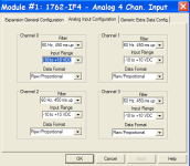
The analog cards configuration shows it configured for voltage -10 to +10 volts with Raw proportional data format. See pdf for raw data values for this configuration.

You said the transmitters are providing 4 to 20ma, how is the voltage developed for connecting to the analog card?

This might give us a clue to how you came up with the offsets and multipliers. It may be an in situ calibration.
 
Last edited:
I'm more on the software side, Toolmandanclassic here is the hardware guy.

The 32767 number i was pulling was just the max signed 16 bit integer, I actually didnt know the analog expansion limited the value to sub 18,000.

If i remember correctly he has a 24 volt power supply in his panel. But I'll toss him an email.
 
Also how is the dip switch set on the analog card? ( its voltage/current dip switch).

Default is current.
 
The analog card is set for 4-20ma use. (It can be either). I used this expansion since the RTU we use only has 2 each 0-10 volt inputs. Since my transducers can be up to 100 feet away, I use only 4-20ma transducers. Some of the cabling comes close to 480 volt running the pumps so cross talk noise is definitely a possibility on the 0-10 volt units.
Mathematics was never my better talent. Therefore I keep a cheat sheet for Ohm's law, can't remember equations well.
:confused:
 
Well if you have a current input and the dip switch(es) is set for current but the card is configured for voltage, I don't know what the data values are going to be. So as stated above you may have just used an in situ calibration for your offsets and multipliers.

You should configure the card for 4 to 20 ma and use an "SCP" instruction.
 
Last edited:
So it is. Been working so far, don't know how, but it has, must be why i had to do the calibration lines in the software.

Toolman said for me to say thank you we have seen the error of our ways haha.

Now we are debating sticking with a method that works for just this set of plants or swapping the inputs over. They have been very accurate on the levels from top to bottom.
 

Similar Topics

Good morning everybody, I hope you are very well. I share with you the information of the PLC LOGO! Siemens and expansions that we have...
Replies
4
Views
1,086
Has any used a ballistic pressure transducer with a PLC? I am not sure if it will capture the event that I need to use as a control. The device...
Replies
2
Views
1,078
I am updating controls on a leak tester, from a SLC 5/02 to Compact Logix. The SLC used a DDV instruction to help scale a differential pressure...
Replies
17
Views
4,414
A little background info I work at a underground coal mine. We have a Dust tank capable of holding 135 tons of rock dust on the surface. We use...
Replies
10
Views
1,629
Hi Guys, Is a typical transducer programmed to output its signal in intervals? Say every 10 seconds it would generate a signal via 4-20mA loop...
Replies
3
Views
1,643
Back
Top Bottom