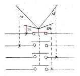
Symbol for 4-position selector switch

kolyur

Lifetime Supporting Member + Moderator
Join Date
Oct 2004
Location
Wooster, Ohio
Posts
1,602
I have to update a schematic to include a 4-position maintained selector switch. The contacts are isolated; there is no shared common as you see in a typical rotary switch.

I couldn't find much online and this is the best I could come up with for a symbol. It seemed to me that one of the contacts should be shown as N.C. since there's no "off" position.

Any other suggestions for how to draw this?
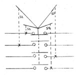
switch.jpg
 
When there is more than 3 positions in the switch, we make a small "truth table" under the symbol for the switch. Trying to display it graphically becomes impossible, especially if there are combinations of several contacts that are active at one switch position.
The graphical symbol then only displays the actuator part with the number of positions, preferably with the text used on the label on the switch.
 
I have to update a schematic to include a 4-position maintained selector switch. The contacts are isolated; there is no shared common as you see in a typical rotary switch.

I couldn't find much online and this is the best I could come up with for a symbol. It seemed to me that one of the contacts should be shown as N.C. since there's no "off" position.

Any other suggestions for how to draw this?

I can understand and accept your schmatic, but I don´t agree with you when you show one contact closed, because all of them are open. You should show all of them in the open position.
 
I don´t agree with you when you show one contact closed, because all of them are open. You should show all of them in the open position.
The contacts are never all open. One (and only one) set is always closed depending on the switch position. I think msp's suggestion shows this more clearly than my original drawing.
 
The contacts are never all open. One (and only one) set is always closed depending on the switch position. I think msp's suggestion shows this more clearly than my original drawing.

I understand you point, but you must go by the rules. If you take apart the switch, ALL contacts are Open and this is how you show them in the schematic. If I look at your schematic, I will think the contact will OPEN when the switch is in position 1. Rules are rules
 
I see your point but what rules are you referring to?

You must show all the equipment in the normal state (no power, no hand operated position etc.).
You say the switch is always in pos. 1, but if the schematic was mine, I could say the switch is always in pos. 4. The schematic is like a language that everyone should be able to read. This is how it works.
 
The schematic is like a language that everyone should be able to read.

That's a nice idea but I've never seen any widely-accepted written standards or guidelines for electrical schematic creation. Can you point me to anything?

I do agree with your comment about components being shown in the "normal" state and I will modify my symbol accordingly.
 
To indicate that you have drawn the switch in the S1 position draw the contacts as you did and use a solid line for the S1 position of the switch and dashed lines for positions S2, S3 & S4.

Edit: I would also have drawn the contact for the S1 position with the horizontal line above the circles representing the terminals to denote a NO contact.
 
Last edited:
That's a nice idea but I've never seen any widely-accepted written standards or guidelines for electrical schematic creation. Can you point me to anything?

I do agree with your comment about components being shown in the "normal" state and I will modify my symbol accordingly.

I have been making and reading schematics for so many years, and this is how it is done. I hope someone in here can shed some light on this subject.
 
To indicate that you have drawn the switch in the S1 position draw the contacts as you did and use a solid line for the S1 position of the switch and dashed lines for positions S2, S3 & S4.

Edit: I would also have drawn the contact for the S1 position with the horizontal line above the circles representing the terminals to denote a NO contact.

Thank you Steve.
 
You must show all the equipment in the normal state (no power, no hand operated position etc.).
Yes, in the normal state as it lies on the shelf (not dismantled!). Kolyur is correct, one position has to be shown closed as it would be if you checked it with an ohmmeter before anything was wired to it. It is also acceptable to draw the top selector with one position a solid line, and then show that contact as closed.

Showing all contacts open helps no one. Then you can't figure out how it operates by looking at the drawing. That is the only goal.

I like your first schematic version best for this switch, Kolyur, along with Steve's suggestions to improve it some.
 
Last edited:

Similar Topics

Hello everyone, Recently, my Archestra IDE shut down while I was editing. After restarting the IDE, I noticed warning symbols under my opened...
Replies
1
Views
101
I was looking for this function, so that i doesn´t need to do it in the PLC. If there are an alarm in the alarm list, i want to flash the...
Replies
2
Views
524
Hello, fairly new to plcs I’m tasked with installing a PE to a micrologix1200, in the attached picture I/14 is the PE I’m installing it’s going to...
Replies
6
Views
942
Hello Thank you all for your support. I am actually experience same issues with TIA portal V17 update5 as well as V18. The problem is with the...
Replies
0
Views
798
Hi all, I've inherited someone else's program and can't for the life of me figure out his use of the # symbol in one of his structured text...
Replies
5
Views
1,919
Back
Top Bottom