relay arcing

paulhomolak

Guest
P
Great Site...First time on it. Looking for a solution to prevent relay arcing, buring/welding up the contacts. The system is low voltage, 24vdc. Polarity remains the same, but it reverse's once every hour for approx. 20 impulses, which is the correction cycle. This is a master clock system. I have read that a diode placed parallel with the load will supress the arc in the relay and to connect the cathode side of the diode to the positive. But since the polarity reverses during the correction cycle will this still work.
Any help would be greatly appreciated.
 
Something simple may work. I have used .01 capactitors across the contacts sometimes with success. Other times, a NE-2 neon bulb. A 24 volt lamp should work, as long as the current draw is small enough it wouldn't hold in a relay or something.

Maybe you can find some MOV's (Metal Oxide Varistors) with a fairly low voltage rating. My understanding is that they are just a pair of zeners back-to-back. A pair of regular diodes (with a high enough rating) may work in series with one reverse to the other.

Is the arcing a product of breaking too big a load, or is it more from discharge of emf buildup on coils. If it is from a large load, a larger contact may allieviate (Not Elinimate) some of the problem.

I have resorted to having a couple of sets of contacts in series that all opened simultaneously to break down some of the arcing. When I learned of this (over 30 years ago), there was a sound explanation of why this worked, but I have long since forgotten it.

regards.......casey
 
I work a lot with power stations and emergency power systems. The closing and opening coils for high voltage circuit breakers sometimes draw very large currents (DC) at the point of inrush. Relays do not look good afetr 1 or 2 switchings. I have seen 15 amp relays sitting in a switchboard with the plastic cases running down the inside of the board like water.

The answer is to use a relay, or in this case a contactor, with 3 or 4 poles connected in series.

The reason for the contact failure is that when DC is switched off, it draws a large arc. AC goes through a "0" volt point where the arc tends to extiguish. DC does not. It just sits there and burns unless there is a big enough air gap to extinguish the arc.

By connecting 3 or 4 poles in series, the air gap is increased and the arc extinguishes properly.
 
Usually when switching DC on inductive loads a clamping diode shunting the load will do the trick, and also cause the coil to discharge/drop quicker. The diode is placed so that the cathode is facing the positive side of the DC power supply.
 
May want to take a look at Solid State relays...http://www.crydom.com/

Technically they dont have contacts to arc, can be switched/pulsed more often and can be used with large loads.

The cost vs performance/reliabity is better, in my opinion, than using electro-mechanical relays.
 
Usually large contactors which are dedicated to switching DC have magnets next to the contact area to force any arc away from the contact extinguishing it.
 
I'm new to this site but have been a frequent reader of threads. Sometimes it is the only thing keeping me up on the nightshift. Check this site for a possible solution to the arcing issue We have a few units that are coming up on 500K cycles with no issues. It was originally part of a PM to change relays. Not anymore.

http://www.mdius.com/relays.php
 
Good God!

I can't believe anyone is still using mercury!

but perhaps that's because I remember mercury arc rectifiers.
 
What is the load? Are the relays rated properly? We use relays to
switch high DC loads all the time without problem. How EXACTLY
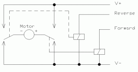
do you reverse polarity (provide picture please)? Maybe it's
not the load but the way you switch. I've seen quite few times
that reversing relays blow up because for an instant they short
power supply. If you use inverting contacts like shown bellow
this problem will not exist and you don't have to interlock relays
by placing normally closed contact before other coil.
It is safe to turn one or the other relay in any order or both at the same time.
Btw. you mentioned "pulses" what is the frequency and duration of those pulses?

motor_632.gif
 
Last edited:
kc9ih said:
A pair of regular diodes (with a high enough rating) may work in series with one reverse to the other.


Just to make sure we are on the same page, both anodes would be tied together with the cathodes attached to +VDC and 0VDC. If I remember correctly, if you do this you need to provide a 0VDC at the anode of both to dissipate the arc. Maybe one of the EEs on this site can verify this.
 
Y'all done gone and got this poor country boy CORN fused.

First and foremost if the arc is so great that the relays fail regularly then there must be a design flaw...either the relays are not rated properly OR when reversing there is a short.

I didnt understand the picture above nor the comment about 3 or 4 pole contactor wired in series....SERIES? Wouldnt you run the power thru in PARALLEL to use all the contacts to divide the current? In series the current would be the same on all contacts AND again if the relay/contactor isnt properly rated it would arc excessively.

I aint sure about using mercury relays in this day, solid state offers a good solution without the hastles in the US from the EPA when you have to dispose of them. Properly sized and rated regular electromechanical relays offer the least expensive option.

In general I would determine the exact load and frequency of the switching then use that information to find a relay/contactor that would work properly. I would also check the reversing part and verify its not locking in both directions for a brief period...milliseconds may not blow a fuse but can burn the contacts. Would be appropriate to attempt to interlock the forward and reverse relays.
 
BOB

You are correct on the diodes, anode to anode.

I have also used zenors, but then that is basically a varistor.


RON

I think the concept of the contacts in series is dividing the voltage among them, not the current. The arcing occurs until the voltage diminishes to the point where it won't jump anymore. With AC, the cyce drops to 0 volts, much less arcing, if any at all. As each contact opens inducing (poor term) resistance, times the number of contacts, voltage drops.

Large (HV) DC contactors have huge ARC Chutes, to prevent arcing to the frame or nearby components. I spent several years with traction drive mining trucks, and with locomotives, brings a whole new perspective to high voltage respect. Mining truck will have about 2000 amps draw when the contactor closes to make the truch start moving. At full speed, when contactor opens (usually for elevator style dynamic braking) the voltage is typically 2400-3000 vdc. All this thru a single 535mcm cable. The lug ends burn off periodically from the heat.


Anyway, I think you get the idea.

regards all.....casey
 
Last edited:

Similar Topics

Hi, I am using AB 5069-L306ERS2 CPU. My system should achieve SIL-2. I have safety door switches connected to AB 5069-IB8S module, and I want to...
Replies
1
Views
108
Hello, I need assistance in making a Relay operation that follows the given parameters: -if S1 is switched and S2 is at off, the Lamp 1 will be...
Replies
3
Views
111
Question to anyone with ideas about my thoughts on upgrading a very vintage timer, which is being used to switch between 2 5hp domestic water...
Replies
14
Views
436
I have an application where I want to use a safety relay in combination with a flame detector as the sensing element. The flame detector has relay...
Replies
23
Views
1,076
Back
Top Bottom