Safety Controller

Tweeker

Lifetime Supporting Member
Join Date
Nov 2007
Location
Smalltown
Posts
79
Hello. I am looking for some strategy ideas in developing a program in a CompactLogix system using the L43S processor. This is an upgrade from a previous SLC processor where SIL3 safety is desired.

I cannot seem to get my hands around the issue of the standard program not being able to read/write to the safety program. I understand why, but if my motor controls are located within the safety routine how do I exercise any control over those same outputs using my standard routine? Should I place everything within the safety task?

Thanks.
 
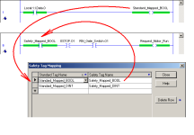
here's a BASIC idea that might help ... from the Main Menu at the top of the screen, click Logic - then Map Safety Tags ...

in simplest terms, this "mapping" operation sort of "ties the two tags together" ...

good luck with your project ...

.

safety_mapping.PNG
 
Last edited:
Thanks for the responses. I did find the tag mapping in the literature. I just wanted to get my post out there in case I reached a dead end.
 
here's a BASIC idea that might help ... from the Main Menu at the top of the screen, click Logic - then Map Safety Tags ...

in simplest terms, this "mapping" operation sort of "ties the two tags together" ...

good luck with your project ...

.

Ron,

I am far from an expert on Safety and have not used A-B in a safety application, but this seems to violate the requirement that Standard or Process Logic not be able to write to Safety Logic. Obviously since this is built into the configuration software, A-B doesn't see it that way, but could you explain your understanding of why this is allowed?

Thanks
You are correct, it does not. That is why we are having to change the panel and control those motors with standard contactors in series with the safety contactors. This will give me control and meet safety also.
 
Greetings JHarbin ...

first let me say that I personally am NOT knowledgeable about "safety control" – and at 68 years old and anticipating retirement – I have ZERO desire to get into that particular field of PLCs ...

regarding your specific question:

could you explain your understanding of why this is allowed?

to be perfectly honest – I have absolutely no idea why ... all I know is that the Original Poster asked a simple question – and I tried to provide a simple answer ...

and I also made an honest attempt to point out that this was just a "BASIC" idea [emphasis in the original] ...

the OP also asked the following:

Should I place everything within the safety task?

personally – I wouldn't THINK so – but to get a definitive answer we'll have to rely on someone who is much more knowledgeable about "safety" than myself ...

it would just seem reasonable to me – that some things located OUTSIDE the "safety" program would need to interact in one way or another with some things located INSIDE the "safety" program ... it seems rather obvious that the "mapping" operation was provided for precisely that purpose ...

and as you pointed out:

Obviously since this is built into the configuration software, A-B doesn't see it that way

I'm tempted to go along with you there ... I'm 100% certain that they know a LOT more about the "safety" subject than I do ...

personally I'm mildly interested in seeing where this particular line of discussion leads to ... I'm starting to see more and more of this "red stuff" included in the program files that my customers' (companies) are sending along with their technicians (students) ... thank you for moving the topic along ...
 
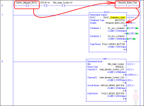
just in an effort to move the discussion along – I wonder if the attachment below would help us understand ...

specifically, the Request_Motor_Run tag that I mentioned earlier does NOT actually make the motor run – rather it just "enables" the ROUT (Redundant Output) instruction ...

and note that there are other "safety" instructions involved – including the RIN (Redundant Input) instruction – and an ESTOP (Emergency Stop) instruction (not shown here) which all must be satisfied in order to make the motor run ...

basically what I'm wondering is this:

does it make a difference if the "safety mapping" technique isn't really CONTROLLING an output directly – but instead just REQUESTING that the safety program turn on the motor? ...

so? ...

.

safety_mapping_2.PNG
 
Last edited:
just in an effort to move the discussion along – I wonder if the attachment below would help us understand ...

specifically, the Request_Motor_Run tag that I mentioned earlier does NOT actually make the motor run – rather it just "enables" the ROUT (Redundant Output) instruction ...

and note that there are other "safety" instructions involved – including the RIN (Redundant Input) instruction – and an ESTOP (Emergency Stop) instruction (not shown here) which all must be satisfied in order to make the motor run ...

basically what I'm wondering is this:

does it make a difference if the "safety mapping" technique isn't really CONTROLLING an output directly – but instead just REQUESTING that the safety program turn on the motor? ...

so? ...

.

Hi Ron,

Thanks for the reply. I work with another Safety Controller that is specifically designed to work in a SIL2 environment. Their design allows the Safety Logic to affect the Process Logic but not the other way around. In other words, nothing that happens in the Process Logic can affect the Safety Logic at all - a tag in the Process Logic can't be used in the Safety Logic. However, a tag in the Safety Logic can be used in the Process Logic.

I have spent several months (off and on) studying SIL/SIS and whatever other Safety Stuff there is out there and still find it interesting how much there is to know, and how much people think they know but might not.
 
In the automotive big 3 world, safety programs are taken seriously and typically require a controls engineer supplied by the customer to sign off on the safety task. They will specifically look at how the non-safe tags interact with safety logic and that the logic is truly safe. Usually the non-safe tags are used for resetting and feedback monitoring. The mapping gives the reviewing engineer a specific place to review what is traded between safe and non-safe tasks.
Once the safety task is approved, the safety signature is recorded and then used to create a fault in the standard logic if there is ever a difference. This has been true with both Siemens and RA control systems.
 
In the end a safety rated plc can do nothing to guarantee that a specific design is safe. This is no different than the days of the hardware safety modules. All a safety plc can do is guarantee that the state of the safety device inputs are correctly reported to the plc, that the safety outputs are truly at the level the plc says they should be at and that the safety logic is definitely executing and is not hung or incorrectly evaluated. That's it.

Going directly to the safety/non-safety interaction point, in the greater scheme of things having a non-safety condition drive a safety output isn't such a crazy thing. Think back to the "old days" where you would have a plc controlling an output but would have the power to the output cut by a safety relay. You may even have had a second device in the output string driven directly off of the safety relay to provide redundancy. That used to be considered "the way to do things". In the end, you were counting on the safety relay to stop the system if the non-safety output went south. This is no different that using a condition from the non-safety section of the program in series with the safety internal e-stop conditions to drive a safety rated output. You are ultimately still relying on the e-stop devices to provide a guaranteed stop if things go bad.

Again, it all comes down to ABSOLUTELY KNOWING if an e-stop actuator is triggered and ABSOLUTELY KNOWING that the desired output action takes place from a hardware and processing perspective. That is what a safety plc and I/O system gives you. Nothing more.

Keith
 
My point of view is similar to Keith's. I use an extra layer of controls. It cost a little more upfront but the troubleshooting time drops way down when the maintenance team has an issue.

I use the safety routine to handle the safety functions. I use the standard routine to hand non safe functions.
The passing of safe and non safe tags can be a huge risk if not handled correctly.

A few examples of what I do so you can make your own conclusions.
my standard safety design for a across the line motor (non VDF) is 2 safety contactors is series rated at the capacity to handle the load. Then a standard contactor in seris wit the safter contactors. The safety contactors are controlled out of the safety logic, standard out of standard logic. Use the tag mapping to map the safety tag (safety output) to the standard logic. In the standard logic use this this as a start permissive for the motor. The safety contactors only open in a safety conditions. Use the standard contact just like you always do..

My reasoning
Some companies don't allow maintenance to look at the safety logic. Sometimes it is just an issue of "we didn't buy that software? We didn't even know it was an option" other times they just don't want them to look. That's not my call it's just the way it is.
My safety contactors only open under a load in an EMERGENCY. When you need to enter. Work cell under normal conditions open the standard contactor first then open the safeties. Let the standard contactor take all of the abuse.

I don't like to handle all of the motor control in the safety while passing tags from the standard because a simple branch in a standard logic can cause an unsafe condition.

Example the maintenance team hasn't be through a PLC BOOT CAMP yet. So the just add a branch (software jumper wire) around all that stuff in standard logic to make the motor run the move. So they add a branch, the safety logic executes the code and writes a 1 in the box. The motor starts good, bad, or otherwise.
 
I don't like to handle all of the motor control in the safety while passing tags from the standard because a simple branch in a standard logic can cause an unsafe condition.

I think of this similarly to the way you do. The Safety Controller that we normally use enforces this by not allowing Tags from the Standard Logic to be used in the Safety Logic. That is the way they interpret the requirements for SIL-2 compatibility/functionality/certification.

I'm not saying anything that hasn't been said before, but Safe Design is the only way to ensure a safe system (if there truly is a way to ensure a safe system). That is why equipment that is certified as SIL-X simply means that it can be used in a safety application up to and including that SIL. Using SIL-3 certified equipment with poor design can be less safe than a SIL-NONE system using best practices.
 
I just wanted to interject what Allen-Bradley states on the subject in the subject:

ATTENTION: When using standard data in a safety routine, you are responsible
for providing a reliable means of ensuring that the data is used in an appropriate
manner. Using standard data in a safety tag does not make it safety data.You
must not directly control a safety output with standard tag data.

Rockwell Automation Publication 1756-RM093H-EN-P page 47 (emphasis added)​

So, the example Ron gave is perfect. The standard side makes a "request" it's up to the safety task to control the output based on ensuring safety, it will honor requests only when it is safe to do so.
 
I agreed with everything that Keith said up until the last item.

Again, it all comes down to ABSOLUTELY KNOWING if an e-stop actuator is triggered and ABSOLUTELY KNOWING that the desired output action takes place from a hardware and processing perspective. That is what a safety plc and I/O system gives you. Nothing more.

They don't even do that. It is important to understand that safety systems are not absolutes. A SIL 2 system only has to work 99% of the time. You should count on the fact that one time in a hundred that e-stop doesn't work.

Modern safety system have a probabilistic design. They are extremely reliable but are never ever absolutely safe. No design is ever 100% absolutely safe.

The reason I'm such a pedantic jerk about this is you never want someone relying on the system to keep them safe. Things such as using an e-stop instead of lockout/tagout. Never rely on a safety system, even a SIL 3 system can be wrong once in a thousand tries.
 

Similar Topics

Hello Everyone, I am looking for AB 1765-L84ES Guard Logix 5580 Safety Controller Online. For testing my program with PLC & HMI, Is there...
Replies
6
Views
742
Hi all, We tried to setup the hardware onto a 10 slot rack as follows, PS Slot 0: 5580 controller Slot 1: Safety Partner Slot 2: Safe Inp Slot...
Replies
8
Views
2,731
Hi all, I want my Red Lion Graphite HMI to be able to read the inputs of a Banner SC26-2DE Safety Controller, connected via Ethernet. Do you think...
Replies
4
Views
1,456
So this is an example safety circuit for a Yamaha RCX-340. I am wondering what the T terminals are on the example safety controller? are they...
Replies
6
Views
3,010
When using an Allen Bradley safety guardlogix controller I know there is a signature needed for the safety aspect of the controller but what I...
Replies
4
Views
6,960
Back
Top Bottom