1771-IXHR/C Setup

mjp123gp

Member
Join Date
Mar 2012
Location
Savannah, GA
Posts
94
Is there any additional software required to setup this module other than RS-Logix 5? I am trying to remotely help someone test his module and I have it setup in rs logix with the block transfers and have a thermocouple connected but I'm not getting any input. I am not there to check the wiring but he says everything is tight and connections are good. Both the write and read block transfers are enabling and i'm not getting any errors. He is testing with a type-K thermocouple that was also used to test a 1746-NT8 and it works fine on it.

One of his repair guys said that this module required additional software but I didn't think that was the case.

Any ideas of something i'm overlooking?
 
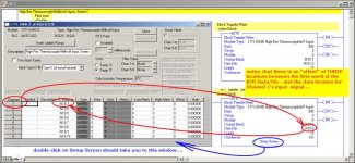
this has bitten quite a few technicians in the past ...

if the information shown below doesn't help, it might be a good idea to upload the program from the PLC and post the ENTIRE file (RSP) here on the forum ... (you'd have to zip it first - forum rule) ...

you might already know this - but the figure demonstrates a very popular misconception ... specifically, the data for Channel 1 is NOT located in the first word of the Block Transfer Read's data file ...

One of his repair guys said that this module required additional software but I didn't think that was the case.

I've never heard of that before ... if that's true, it would be my "learned something new today" experience ...

good luck with your project - offline for tonight ...

.

ixhr.jpg
 
Last edited:
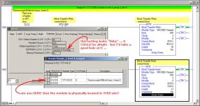
Thanks for the response. I got that far, I had him go down the terminal strip to try other inputs but still got nothing. When I added the module in the I/O configuration I used the insert ladder button so it created the BTW and BTR for me and looks like it used the same addresses you have on the example. I double checked everything in the logic that was created and I didn't see anything wrong.

I have attached the file. It is using a 1771-IXE/D module(NOT the 1771-IXHR) which is also giving me the same problem. I can't really check his wiring but I want to make sure i'm not doing something wrong in the program.
 
I have an IXE card in my lab equipment which was just given to me as a "defective" unit ... if I remember right (it's been about 15 years ago) it gave the same "won't do diddly" symptoms that you're seeing ...

I opened it up and found a FUSE which had been blown ... it's about the size and shape of a 1/4 watt resistor - but was colored a solid green color ... it's soldered to the main circuit board ... I got a pigtail fuse holder and soldered around the green fuse - and plugged in a 1/4 amp fuse (just guessing on the value) ... the module has been working fine now for about 15 years ...

of course I only use my stuff for training - so proceed with caution ... but I'd be suspicious of the fuse ...

got to go now - good luck ...
 
one more WILD GUESS ...

make SURE that the onsite technician you're talking to realizes that with a PLC-5 system, you do NOT count the processor's slot as Slot Zero ... specifically, the processor's slot does not get counted at all ...

some techs who work mainly with SLC-500 systems get this wrong ... with that platform you DO count the processor's slot as Slot Zero ...

again - I'm just guessing - but as far as I can tell from here, everything that you're reporting could be related to having the module's slot in the chassis counted - and therefore entered - wrong ...

this time I am REALLY offline for tonight ...
 
He has the power supply(1771-P4S) in the very last slot of the chassis. The IXE module is the next slot to the left towards the zero slot. Should that be slot 2?

If the module was in the wrong slot wouldn't the BTW instruction get an error?

Also on the EEPROM- Transfer at power up setting, would that matter if I manually enabled the BTW after startup to re-write the configuration?
 
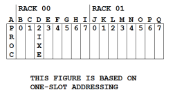
sometimes it helps to LETTER the slots ...

below I've shown a 16-Slot Chassis (yes, there are 17 actual slots) ... if your chassis is smaller, just ignore the appropriate number of slots at the right end of the sketch ...

notice that I've LETTERED ALL OF THE SLOTS (even the processor's) - A through Q ... this helps remove the ambiguity of "which-slot-is-which-number" when you're dealing with someone over the telephone ... (in an earlier lifetime, I spent about eight years as a telephone "answer man" - mainly helping people with PLC-5 systems ... I know what you're up against - and I feel your pain) ...

according to the program that you posted, the IXE module should be located in the slot which is lettered "D" ... the PLC-5 processor should be located in SLOT A ...

suggestion: have your tech on the phone "count" ALL of the slots (even the processor's slot) - going from left to right ... A, B, C, D, and so on ... if the IXE module is NOT located in "Slot D" then you need to correct that discrepancy before you go any further ...

I'm not sure about your other questions - but I can check them out when I get back to my lab ... that will be at least a few days from now ...

.

ONE_SLOT.PNG
 
Last edited:
something else to consider ... sometimes these older system don't make good contact between the module and the backplane ... it often helps to slide the module in-and-out-and-in-and-out several times to "wipe" the connection ...
 
Thanks for the help Ron. I finally got him to send me some pics of his setup and he DID have the module in a different slot than what he was telling me. I changed the addressing and it's working. Guess hat also answers the other question I had about the BTW getting an error if the module address is incorrect.

Thanks again
 

Similar Topics

we are looking to purchase spare replacement parts for our plc-5 system...as I'm sure you all know some cards aren't as easy to come by as...
Replies
1
Views
1,340
I was just asked to track the temperature in a couple rooms where we have some PLC-5/40's and some HP servers. I found these 2 Thermocouple...
Replies
2
Views
2,071
Preface: Kinda long, so I made section titles Intro: I just want to see if anyone here has seen anything similar. A PLC5-40 series C enhanced...
Replies
3
Views
360
Existing environment shown in attached photo (Existing.jpeg) Proposed Environment shown in attached photo (New.jpeg) I am migrating a PLC5 system...
Replies
0
Views
585
I have a 1756-L81e v32 using a DHRIO v7.001 in RIO scanner Driving (7) 1771 ASB Modules @ 115k baud. The Racks RPI are set at 48msecs. This system...
Replies
2
Views
889
Back
Top Bottom