new to forum and programming

thoresonr

Member
Join Date
Jun 2015
Location
Amherst NY
Posts
3
Hi everyone. I have worked with OMRON plc's and know my way around the logic for troubleshooting, but i have no real experience programming from scratch. I am using a NB5 HMI screen to interact with a CP1H PLC (relay i/o). How do I figure out the input addresses? The output addresses are Q:100.00 and on, but using I:0.00 does not indicate an input when made.

Also, which program device is used to read analog voltage signals? There are A/d and D/A I/O on this plc, and ive wired them as such, but am unsure on how to actually read and manipulate the data.

Also has anyone here bought the coursework from this site and is it helpful for this type of PLC's and software?
Programming software is CX-ONE lite (CX-programmer) and NB Designer for the HMI screen (NO IDEA how to use)

Thanks for any input you can give me

Rob
 
Here is the programming manual:
http://industrial.omron.com.br/uploads/arquivos/CP1L(H)_2007_W451-E1-03_PROGRAMACAO.pdf

To address the CIO do not use I:0.00 just use 0.00. CX-one will use I:0.00 as the symbol for an address instead of the actual address.

Here is the brochure on the CP1H and NB5.
https://echannel.omron247.com/marcom/pdfcatal.nsf/D44E98EB443C2C84862571BF005F12EF/$FILE/CP1H_datasheet_en_200803.pdf
http://industrial.omron.com.br/uploads/arquivos/nb_v412_csm1002572.pdf

Just do a search for the manuals that you require. Note: There are usually installation as well as programming manuals.

Here is a good reference to programming Omron PLC's using Syswin.
http://www.mikroe.com/old/books/plcbook/plcbook.htm

Here is just one CX-One Programmer Tutorial:
http://read.pudn.com/downloads157/ebook/700257/CX-Programmer%20Tutorial.pdf
Do a google search to find additional information.

Welcome to the forum,
Garry
http://www.accautomation.ca
 
If you have a CP1H with the built-in analog I/O your analog inputs are CIO addresses 200-203 and the outputs are CIO addresses 210-211. The documentation is in section 5-5 of the W450 manual.
 
Thanks for those resources. It has helped a lot.

Onto another question. I have an NB5 hmi and I have made some simple momentary start and stop buttons which are addressed correctly in my .cxp program. However, when I push the start button, I see the rung light up but my output wont latch or engage. If I set, or force it will engage. I do have a latching contact addressed the same as the output for this feature, but the green light just shoots over my output coil from the pushbutton and wont engage the coil.

Any suggestions?
 
One thing that will cause what you are seeing is to make a program change in CX-P but not download it to the PLC. In that case the logic in CX-P is satisfied but the logic in the PLC is not.
 
However, when I push the start button, I see the rung light up but my output wont latch or engage. . . .I do have a latching contact addressed the same as the output for this feature,. . .
Because you have little programming experience, it sounds like you may have 2 Outputs for the same address. The last Output version in the PLC scan cycle wins the race, and the first one will have no effect (the double-coil syndrome). Search on this site for "double coil" and you will find pages and pages of posts about why not to do that.
 
Last edited:
I have an NB5 hmi and I have made some simple momentary start and stop buttons which are addressed correctly in my .cxp program.
You should tell us all what addressed correctly means - what is the exact address?

I do have a latching contact addressed the same as the output for this feature, but the green light just shoots over my output coil from the pushbutton and wont engage the coil.

Again, what address are you using?
Also, 'shoots over the output coil' doesn't have any meaningful info. What is that describing?
 
Thoresonr,
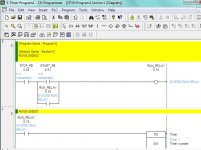
If you are having trouble with your Stop-Start Output, set up a System RUN Relay similar to the attached picture. Use a seal-in contact in parallel with the Start PB, instead of a Latch instruction. Use physical or HMI NC Stop and NO Start momentary pushbuttons.

Omron CX-Programmer Start-Stop Relay.jpg
 
Last edited:
working... sort of

Thanks for all your input on this. I am unsure how, but I recompiled the .cxp file and redownloaded to CP1H. All works now. I am using the NB5Q HMI to start and stop the motor, and turn on coils. It's a bit ugly (I am still learning NB designer as I go) but it works for now.

My next dilemma, is I am using a FB to read an LVDT position 0-10vdc and it gives me outputs(i think they are at least) in REAL, INT, and WORD formats. My servo card needs to see positive voltage to drive the servo in one direction, and a negative voltage to drive it the opposite direction. I know the DA outputs can be scaled -10 to 10vdc but not quite sure how to make the FB understand what I want, or if I need another FB to do this. ( I am quite new at FB's)

Many thanks,

Thor
 

Similar Topics

  • Locked
  • Sticky
Hi folks, If you're having any login issues kindly send an email to [email protected] or use the 'contact us' link on the bottom of every page to get...
Replies
0
Views
1,063
Hi Folks, After many, many hours of setup/testing/tuning/etc I'm happy to announce our brand new shiny PLC forum is coming out of beta and...
Replies
30
Views
2,123
Hi All, Firstly… Merry Christmas to all of you! Secondly, as some of you may have noticed I made some modifications to our backend to address...
Replies
29
Views
7,075
For the past 2 days when I come here it stops on a Verification page to see if my connection is secure, Clicking on a thread goes to the same page...
Replies
1
Views
356
Hello, Whenever I google some bug regarding simatic step7 or siemens PLCs, the first results are usually from siemens support website. But when I...
Replies
2
Views
557
Back
Top Bottom