PLC Controled Elevator

BDF

Member
Join Date
Jul 2004
Posts
1
To whom it amy Concern:

I am currently a student at the college of The North Atlantic and am currently working on our tech thesis which is a PLC controlled Elevator. I have a program written for it but am currently waiting on I/O modules in order to try the program. I was wondering if someone could look at the program and give me some feedback.

The system consist of a three floor elevator and being controled using a micrologic 1500 PLC.

Thanks,

BDF
 
Couple of quick thoughts.
I like the fact you at least divided it into sequences somewhat but I would prefer more definitive comments/labels on the addresses.

The N files are normally used for integers, B (binary) files are normally used for bit manipulation. Not a real issue because any word file can be used for bit manipulation, just letting you know the common procedure.

I havent looked real close yet but I am somewhat confused about how the doors open with the Pushbuttons and/or if they open automatically when a floor is reached. I will look closer as time allows but take a look at your PB4 and N7:10/3 and their use.

At least you made a strong effort before posting, many of the pro's with RSLogix500 will probably take a look and advise in more detail.
 
Hi. I agree with every one above for the documentation.
Symbol PB1 is too vague, try the symbol "Floor_1_Req_PB" with the description of "Pushbutton on the operator console to request car to travel to level 1"
Then add a rung comment to describe what is happening. ie When operator presses the button to request the car to travel to floor 1 we latch a bit to indicate there is a valid travel request"

There is no need to remap all your inputs to binary bits, ie use the limit switches in the program. For example rung 11 does not need to map the limit switch to a bit.

What is the difference between rung 0 and rung 7. ie what PBs are internal to the car.
Rung comments and better descriptions will help to clarify.

Study the relationship between bits and words.
ie b3:0 is a binary word where b3:0/0 and b3:0/1 etc are bits of the word. For a valid call for the car to travel to floor 1 set individual bits of b3:0 then if B3:0 is not equal to zero (that is any bit is set) then there is a valid travel request. to cancel the request just clr the b3:0 word.

Use the verify button. You missed some addresses which this test will pick up.

When you add a branch around an instruction and you wish to add a lower branch try to right click on the left lower corner of the branch to give it focus, then right click for the menu, select extend branch. Notice the difference. This branch style is virtually unlimited, executes faster than the indented branches and uses less memory.


I posted a quick couple of rungs of code to give you a rough idea of what I mean. This is not a working example just a collection of ideas.
It is not zipped, just change the extension to RSS and open. Sorry to those who dont have 6.10.10.

Thats enough to get you started. Regards Alan
 
Last edited:
Example:

The lack of some programmer's use of the "right click extend branch" is a pet peeve of mine.

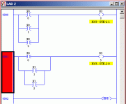
Here is an example of what Alan is talking about:

[attachment]

The first rung (as seen by the PLC)
BST XIC B3:0/0 NXB XIC B3:0/1 NXB XIC B3:0/2 BND OTE B3:0/3

The second rung (as seen by the PLC)
BST XIC B3:0/0 NXB BST XIC B3:0/1 NXB XIC B3:0/2 BND BND OTE B3:0/3


Notice that there are a couple extra instructions, an BST (branch start)and a BND (branch end) in the second example.

rsl_branch.gif
 
Bummer! I dont have the software to look at it myself. I can only hope that some day AD, or GE will get into the university class room....
 
i have not looked at the program yet but a good learning program
to try out is Logixpro from thelearningpit.com

when i first started plc this was an invaluable tool. it is worth it's value many times over.

it mimics rslogix and also has simulations you can download your program into and test it out to see if it works..visually.

you can download a free trial copy but i would buy the cd version

hope you try it

(it has an elevator simulation in it)

mark
 
REALLY??? Cool. I thought this was just a style thing.

Just an clarification on something that bit me when I was first learning...... If you don't use the extend branch, you are limited in how many branches you can have in that rung.(5 in a 5/04) In the same 5/04 you can have up to 75 extended branches.
 
Last edited:
So...

What's the advantage in having both types available?

Could it be that the compiler doesn't know the difference between a new branch and an extended branch?
 
I've often wondered the same thing. When would you want to use an indented branch? What is the intended purpose, what is the advantage?

Another point, if you come across an indented branch and you want to change it to an extended one: click on the left side of the indented branch and drag it up to the left side of the branch above. Two small red squares will appear on each side of the vertical rail, continue to drag the highlighted rung onto the left-most (little) square until it turns green, then release the button. You'll notice a few more little red squares appear in the area, experiment dragging unto each one.
 
Terry Woods said:
So...

What's the advantage in having both types available?

Could it be that the compiler doesn't know the difference between a new branch and an extended branch?

The compiler knows fully well the difference betwee the two.
The code will execute the same.
A reason to use the "unextended" type of branching is that you can easily insert an additional instruction:

-------||-----------()
| |
| |
------||------
| |
| |
----||----


-------||----------------()
| |
| new! |
---||------||------
| |
| |
----||----


If there is no risk of that, I normally use the "extended" type of branching. Mostly because it looks better ;)
 
Real Elevators....

BDF,

I took a look at your program, and I would say it represents a very good guess as how a real elevator works. However.....

If you were to build a working model to simulate your elevator, you would find that your concept requires quite a bit of IO and much human intervention. So let me explain a few things..

Door operation:

There is only one door open/close circuit for all floors. All the door locks are wired in series, so there is only one input there. Also the door "unlocking" and opening/closing device (door operator) rides on the elevator car, (in the case of passenger elevators). As the car door opens a clutch mounted on the car door unlocks the landing door and pulls it open with the car door. The door operator requires Outputs from you program for Open & Close, and requires inputs for open limit, and close limit.

Positioning:

There usually a sensor box on top of the elevator car that would have 5 sensors: (Known as the Selector) They are UP Count, Down Count, UP level, Down Level, and Door zone. These sensors are used for all floors. And for the sake of this project (keeping it simple), they are prox switches operated by metal vanes mounted in the elevator shaft.

Selector operation.

UP Count: placed between floors activted when sensor passes it, incrementing UP/Down counter in program. (UP/Down counter keeps track of what floor your on). Also initates slowdown for next floor if a call is in for that floor.

Down Count: Same as above but in down direction.

UP Level: There is a single 6 inch vane at each floor level. The Up level sensor brings the car into final level at the floor. when the sensor come off the top of the vane the elevator stops, and the doors open.

Down Level: Same as UP Level, but works in down direction, and stops elevator as sensor comes off bottom of vane.

Door Zone: This sensor is placed vertically between the up and down level sensors and is active with the elevator at the floor level. this sensor allows the doors to open (safety issue)

Direction Prefrence:

There are two rungs in your direction prefrence circuit. Each rung will end with one relay called either CA for Call Above, or CB for Call Below. Actually for students this seems to be the biggest bridge to cross, but the concept is rather simple.

Your UP/Down position counter will activate position coils (1F, 2F, and 3F), by way of comparision contacts. N/C contacts from these coils will be placed in series will the latched call contacts to provide direction prefrence. Like so.


2C 2F 3F CB
--||--|/|--+--|/|-----|\|------(CA)
|
3C |
---||------+


Motion:

Once you have a direction prefrence, (CA or CB), the motion will be initated by a up or down, and high speed output. (for this example we will only work with two speeds in either direction). The Direction output will be active when the door closed limit and door lock inputs are active. Like so.


door lock door close limit CA DOWN UP
--||---------------||-------------||---|\|-------( )


If you can get these concepts togeather and working, the gory details of interfacing the door operation, motion, and direction prefrence etc.. should be more obivious and fall into place for you. Post any revisions and I'll be glad to help with them.

Have fun.

Mike
 

Similar Topics

Good day, I have a main line and two merging conveyors at 45*. _____\_______\_______ Does anyone have an example for "priority merging"...
Replies
6
Views
2,965
Hy! I am mecanical engineer and i want to build potato weighing machine,but i don't have expirience in plc programming. I want your's minimum help...
Replies
10
Views
2,584
Hello every body, For power plant station, there are RMS "Reducing & Monitoring Station" controled by PLC Siemens S7, and the main control...
Replies
0
Views
5,854
HI i would like to know how to get a variable that will store the amount of times a program has been executed. The issue is I have 3 DBs for 1 FB...
Replies
2
Views
50
I haven't encountered problems connecting to a PLC through VM Ware but I am with this particular machine. I'm running Windows 7 on a Windows 10...
Replies
7
Views
95
Back
Top Bottom