Motor positioning problem

amiklic1

Member
Join Date
Jun 2015
Location
Dubai
Posts
12
Hi everybody,

I am new to the forum and I would like to ask apractical question about the issue I am experiencing in one of my projects.

Hopefully someone will be able to help.

I have a 220V motor which is used to travel a trolley over a certains distances over which I want to perform a certain number of stops. Usually it's 4 or 6 stops (incl start and end position).

I use FX - 1s - 10MR – ES for 4 Stops and FX - 1s - 14MR – ES for 6 Stops

The signal I am feeding as a reference rotation count is through double magnet switch on the rope pulley, with two magnets /so every rotation has two signals) and it's working pretty well.

I have, however, a problem in that that's not exactly precise. Sometimes it's stopping on the exact location as it should but sometimes (randomly) it's going for 0-20cm beyond or is that much short.

Now I am thinking to use a kind of an rotary encoder for that but as I do not have much experience I wanted to ask more knowledgeable ones which way to go.

So, I need the stops to be really precise, in let's say 1cm distance, which is possible, for sure.

Other way I was thinking of is to increase a number of signals (magnets on the pulley) to give a higher count number. Would that help?

Thanks in advance!
 
How many counts are you getting for 10mm (1cm) of travel?

Are the counts correct when it stops? If not check to see that you are not triggering faster than the input can switch, and "missing" counts. Also check that the mechanism can physically stop when required, and is not overshooting the position (Part of this would be to check that it's consistent and not undershooting the position).

If the counts are correct when the trolley stops, then you've got some positioning error in the system. The way you describe "rope pulley" you probably lose accuracy over start/stops and direction changes, as you may have backlash, play or tension to deal with.

If the system has a lot of play in it mechanically, a higher resolution encoder or resolver is not likely to help. Is it possible to put a sensor at each location to stop on?

Can you give us any more information? Speed/Freq? Gearbox/Ratio? Final drive ratio? Distance per count?
 
How are you powering the motor? If you are using a variable speed drive, one strategy that may help is for you to switch to a slow speed when you are near one of the stopping points. This is not the most ideal method, but can be good enough when your budget is limited and the cycle rate can be sacrificed slightly to get "close enough". Of course you need enough pulses per centimeter that if you stop within one pulse, it is still good enough.
 
Hello!

Thanks for your answers.

Here are some details and explanations what you asked for:
1. I am not sure about the signals per cm as I have pulley of approx 10cm diameter and two magnets on it. So, let's say that travel from one signal to another is around 125mm. That's why I thought to use either more magnets or change the system to a rotary encoder (which I am not sure how to do :-( ).

2. The error in the signal counts is random, as I see, but when it stops to a certain position it does not show the exact set count. Let's say it should stop on 70, than on 140, than on 200.
Sometimes it stops on 76, 146 and 206 (on all positions the error is the same).
Than for quite some time it stays like that, but over many travels it just change the count number.


3. Rope pulley and the mechanical parts are tight, no loose parts and no "play" and I am going to check the rope position on the pulley with the paint, just to prove it's not sliding (but if it's sliding than the error will always be a negative stop position).

4. I am, in fact, slowing down the trolles when it comes 2m from the stop position. It slows down nicely, but always have an error in position :)

5. I am using VFD Commander SKA1200075

6. Motor I use is Leroy Somer / LS80L 0.55kW 230VD/400VY 50Hz 4Pole IMB3 IP55 IC411 Class F

7. I use two magnets on the pulley and magnetic switch Honeywell SS466A Latch 1811457 HALL EFFECT LATCHING

I can install sensors on each stop. One for the slowing position and one for the exact stop position. I was thinking about that, also.

Hope somebody will be able to help so I will not have to change the entire system upside down.
 
Last edited:
- A 100mm Dia pulley equates to a circumference of ~314mm.
- 2 magnets on that means each count is half, or 157mm.

This is why your stops seem "Random". Being even 1 count out is 150-300mm in stopping position. That resolution won't work if you want to position to 10mm. To get an accuracy of 10mm, you need ~30 magnets on your pulley, which isn't likely to happen. Exit magnets on the pulley solution.

Let's get some more info before we go spending money on "solutions". Does the motor have a gearbox before it drives the pulley, or does it drive the pulley directly? How far between the stops?
 
Last edited:
Pulley is 100mm, but the magnets are on 80mm circumference, so it's 125mm.
Anyway, that's it.
The error is so small in each turn, but significant overall.

I have stops on 10m, 15m and 25m on one system and 10, 15, 25 and 50 on the other.

Anyways, I want to do a bigger system with up to 100m distance stops.

Motor is driving pulley directly, no gearbox.
 
Last edited:
Does the motor actually run at 50Hz nominally? I would be looking at the solutions mentioned.

1) Sensors around stopping positions for deceleration and stop.
2) Something like an incremental TTL/HTL 24V Encoder. If you use this, you have to make sure your inputs can handle it, or you have High-Speed or Encoder inputs.

Also make sure you are running the drive in sensorless vector mode with a braking resistor, and the stopping mode as ramp.

perhaps someone else has some other ideas?
 
Last edited:
Yes, the motor is running on 50HZ nominally.

1) Sensors around stopping positions for deceleration and stop is a good thing, but for the lenghts I have it will take significant work. It's however, easy to make apart of labor involved. That way every deceleration point will have one count and every stop will be second. I can put as many as I want, and that's good.


2) TTL/HTL 24V Encoder is even better but will go beyond my knowledge of the matter.
 
If I go with incremental encoder, how would that imply to the overall system.

I do not have much experience in electronics, mostly mechanics and electrics and this system programming was done by other guy for me.

I guess I cannot just use encoder instead of the magnetic sensor, but what would be the easiest way to exchange one for another.

Hope I could get an idea here and learn more about it.

Thanks guys, you already helped a lot to figure out what's happening.
 
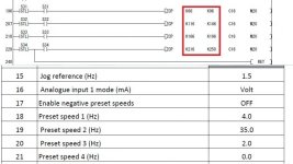
In the file below you can see the preset sensor triggers for 10, 15, 20 and 25m stops.

66-96 is slow don-stop for 10m
116-145 is for 15m
166-196 for 20m and
216-250 for 25m stop.

Below that you see a VFD settings table, with different frequencies which are giving the result of different motor speed.

I said abouve it's VFD driven motor, maybe you haven't figured out.
So it's not 50Hz all the time. I can make it even slower, but the resolution of the signals is still too low.

Speed 1 is slow speed before stop on 10, 15, 20 and 25m.
Speed 2 is the full travel speed
Speed 3 is the speed before stop on the initial position (when the troley is coming back).

I hope this helps.

Best!

Untitled.jpg
 
So, from everything said, after some brainstorming I think the best would be to use the rotary encoder and pick the signals from it.

The cost will not be so high as I might get exactly what I want.

No need for a really high resolution, but I see the encoders come in high p/r such as 400, 600 and above.

I've found 100 p/r one and guess that's enough.


Now the tricky part. If I use the rotary encoder, let's say of this type:
http://www.ebay.co.uk/itm/new-omron...801?pt=LH_DefaultDomain_3&hash=item19f8622841

How to set it up to work with the existing PLC input where currently I am feeding the magnetic sensor signals. Possible?

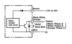
From it's diagram I see that 12V +/- goes to brown/blue wires while signal goes to black/white/orange (as a different phases) and blue.

I guess I will need additional electronic elements to make it working, so if anyone has an idea, I'd really appreciate any help.

Best!

Untitled.jpg
 
Hi guys,

I would really like some input in order to start solving this issue.
Setup does not have to be budget but price matters, of course.

I was thinking of using rotary encoder in a way which will give a signal to tle plc, just like the magnet switch is doing now. Possible?

Sorry if the question might be dumb, as I sad it's not my area of expertise.

Thanks for any help in advance!!!
 
According to the FX-1S documentation, you can use a single phase high-speed counter up to 10kHz (Please double-check the datasheet for your hardware). For what you're doing with about 1,000rpm on the pulley/motor and a 100p/r encoder, you'll get about 1.6kHz back from the encoder at top speed.

Unless I've messed up the calculations, you should be able to use a 100p/r incremental encoder with a high-speed counter to get better control of your system.
 
Ok, just what I meant. Now I will make a simple schematic about how to connect it electrically for others to confirm. Mechanically it will be easy as I can put it on the same axis of the motor pulley.

Should not be hard to do, guess, and the result should be much more precise than with the two magnets and switch ;-).

Thank you!!!
 

Similar Topics

We have now a working installation that is a big 'jar' of liquid cupper (100ton). It is rotated by a hydraulic motor on each side of the jar. The...
Replies
12
Views
2,764
hi I have a Centerline system for carpet. I control a DC motor with digital outputs (relays) (forward-Reverse). I have a Bero Sonar for...
Replies
0
Views
1,786
hi folks, m workin on Mitsubishi Servo amplifier MR J2 S20A & Servo motor of 200 w (mitsu make)....I have configured the whole application &...
Replies
17
Views
18,777
C
did anybody face the problems of the servo motor overshoot when stop and turning back to the stopping point again. I m using the mitsubishi servo...
Replies
2
Views
8,227
Hello, It is mandatory to use VFD IF i use IE5 electrical motor? What happens If connect it directly as delta without VFD? Please look at motor...
Replies
1
Views
120
Back
Top Bottom