PLC-5 1771-IFE maximum scaled value

williamlove

Member
Join Date
Jul 2007
Location
phoenix
Posts
59
My question is, when there is 10V on the first channel of an 1771-IFE card, what decimal value will show up in the data file word (happens to be N7:104) assigned to channel 1?

Here are the configuration words I think are relevant to my question:
Word 1 (Input range): 0-10V.
Word 3 (Input Type and Data Format): Single ended inputs and two's compliment binary.
Word 7 (Scaling max): 9999 (BCD).

I assume this is an easy question but I don't know the answer and I need to in order to convert a program. Thanks!
 
Last edited:
I just want add, I am working with an uploaded program that runs fine. I will convert it to Logix. The manual describes 9999 as the largest number you can enter for the scaling max but since you enter it in BCD I'm confused by it. I think this is a simple question, but I want to know if anyone knows the answer, unambiguously and with certainty. I think the answer to my question is probably that when 10V is on the channel I will see a decimal value of 9999 in the word assigned to that channel. But again, the fact that it is entered in BCD is making me wonder and so I decided to ask.
 
we can't really answer your question without knowing more about how your system is set up ... a screen shot of the module's existing Configuration Screen would be the best way to nail this down ...

but ...

I am working with an uploaded program that runs fine.

that "works fine" part should make it practically painless ...

I will convert it to Logix.

set up an array of INTs (specifically, not the default of DINTs) to match the layout of the INTEGER configuration data that your PLC-5 system is currently using for its Block Transfer Write ... then MANUALLY transcribe the data values directly from the PLC-5 data table into the corresponding locations in the Logix array ... don't "drop a stitch" - go word by word ...

secret handshake: don't worry about the BCD thing ... as long as the module is already working correctly - with WHATEVER values it's been getting - then it should continue to work with the same values in the Logix system ...

naturally you'll need to set up an MSG (Message) instruction in the Logix system - but configure it to act like a BTW ...

repeat: make sure that you're using INTs and not DINTs ...

DISCLAIMER: this is all based on a "best guess" as to how your system is working ... if this doesn't help, then it would be best to post BOTH the existing PLC-5 project file (RSP) - and the new Logix project file (ACD) ...
 
We're not retaining the IFE, we're replacing it with a 1756-IF16 card in the ControlLogix.

My ultimate aim and really my sole aim is to get the EU scaling values so I can enter them in the High Engineering and Low Engineering fields on the Configuration tab of the 1756-IF16.

So my question is, when you utilize the optional scaling feature in the old IFE card and enter a scaling max in BCD, and when that value entered is the max possible (9999 BCD), what value do you get in your analog input value when the voltage on the channel is at full scale (10V)?
 
Last edited:
So my question is, when you utilize the optional scaling feature in the old IFE card and enter a scaling max in BCD, and when that value entered is the max possible (9999 BCD), what value do you get in your analog input value when the voltage on the channel is at full scale (10V)?


Do you know how the device that provides the 10volts is scaled? ( engineering units) e.g. 0-100 psi = 0-10 volts
 
If I knew that I would have the answer I seek. But 10 volts is 10 volts regardless of the nature of the device producing it, right? The question is what does the PLC do with it.

Let me ask the question this way: If a signal generator is used to produce 10 volts across the terminals of an input configured as follows, what value would show up in the data table?

Word 1 (Input range): 0-10V.
Word 3 (Input Type and Data Format): Single ended inputs and two's compliment binary.
Word 7 (Scaling max): 9999 (BCD).
 
Nothing is ever simple in Rockwell-land...

The 1771-IFE is 12 bit and raw data (unscaled) will be 0-4095

Only in PLC5

When you create a BTW to write configuration to the module and a BTR to read back the data, you can then carry out scaling of each channel by double clicking on the BTW "setup screen", where you specify the description, V/C range, and Min/Max for each channel.

Convert to Logix5000

All the above settings become invalid when you go to Logix5000, as BTR/BTW do not then exist, but become MSG instructions (I think). I do not have the code handy to show me how it was done, as we had a 3rd party carry out the automatic conversion. We did away with the 1771 racks at that point, so the analog cards became new hardware as well.

To summarise, you are maybe best to take the 0-4095 per channel and scale using mul/div instructions in the ladder diagram.

If you are changing to the 1756-IF16, it is 16 bit resolution, and if you read the manual - 0v = -32768, and 10.54v = +32767, or 65535.....
 
Last edited:
If I knew that I would have the answer I seek. But 10 volts is 10 volts regardless of the nature of the device producing it, right? The question is what does the PLC do with it.

Let me ask the question this way: If a signal generator is used to produce 10 volts across the terminals of an input configured as follows, what value would show up in the data table?

Word 1 (Input range): 0-10V.
Word 3 (Input Type and Data Format): Single ended inputs and two's compliment binary.
Word 7 (Scaling max): 9999 (BCD).

I don't know the answer to your question as I have never used the "BCD" configuration. But sense you do, why not connect 10 volts to the channel and see for yourself?

See pdf for what the manual says..
 
Last edited:
Its a running system but its 2000 miles away and I can't try it. I appreciate the time you guys (Mickey and John) spent and I have been pouring over that manual which is why I know what words 1,3, and 7 are. But I just need to know if anyone knows what is the largest value an analog input will produce when scaled to produce the largest possible value. The answer is probably 9999 but I'd like for someone who actually knows to tell me. As a bonus it would be nice to know why the scaling max HAS to be entered in BCD. I already know you get 4095 if you don't use the scaling but what about when you do use the scaling, what is the largest number the input can reach?
 
Its a running system but its 2000 miles away and I can't try it. I appreciate the time you guys (Mickey and John) spent and I have been pouring over that manual which is why I know what words 1,3, and 7 are. But I just need to know if anyone knows what is the largest value an analog input will produce when scaled to produce the largest possible value. The answer is probably 9999 but I'd like for someone who actually knows to tell me. As a bonus it would be nice to know why the scaling max HAS to be entered in BCD. I already know you get 4095 if you don't use the scaling but what about when you do use the scaling, what is the largest number the input can reach?

You know, there is a manual for this, right? 1771-UM665_-en-p.pdf.

Yes, the MAXIMUM value you can enter for the scaling is 9999. And the scaling has to be entered in BCD because that is how the module was designed. Even if the data format is one of the binary formats, if scaling is used, it is entered in BCD.
 
The scaling values are entered in BCD ONLY if you're entering them directly into the BTW data table. If entering them on the module configuration dialog box then the values are in decimal.
 
My question is, when there is 10V on the first channel of an 1771-IFE card, what decimal value will show up in the data file word (happens to be N7:104) assigned to channel 1?

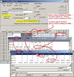
the locations that I used for my experiment are different – but the results should be the same ...

Here are the configuration words I think are relevant to my question:
Word 1 (Input range): 0-10V.
Word 3 (Input Type and Data Format): Single ended inputs and two's compliment binary.
Word 7 (Scaling max): 9999 (BCD).

you didn't specify the Scaling Minimum value ... I assumed it to be 0 ...

I assume this is an easy question but I don't know the answer and I need to in order to convert a program. Thanks!

it would be a LOT easier if you had posted your ENTIRE program file for the old PLC-5 (RSP) ... the results shown below are an experiment that I just ran with actual hardware ...

I'll be honest – I have NEVER seen anybody use the 9999 (BCD) maximum scaling value that you mentioned in your original post ... I'll keep the gear hooked up for another day or so ... if you'll post the RSP file, I'll run the experiment again using the actual values from your file ...

IF (big IF) the GUESSES that I've made are correct, then I've got a serious hunch that you're going to have problems with that 0VDC input signal giving you a data reading of 5000 ... that just doesn't seem right ...

suggestion: post your RSP file ...

good luck with your project ...

.

TRY_IFE_2.jpg
 
Last edited:
We won't know until he post the program but with a -9999 in the raw min would probably give a zero count with 0 volts. Just a guess as long as we are guessing here.
 
Last edited:
Here are the configuration words I think are relevant to my question:
Word 1 (Input range): 0-10V.
Word 3 (Input Type and Data Format): Single ended inputs and two's compliment binary.
Word 7 (Scaling max): 9999 (BCD)

Wow, this thread makes me feel old.
The IFE scale values are in BCD, there is a min and max parameter.
There are separate sign bits, so you can scale the input from -9999 to +9999
The data coming back from the module may be set to be either in BCD or integer (2's complement).

So if the input is 0-10V, and the min scale value is 0, and the max scale value is 9999. You should get
0V = 0
10V = 9999

If the input signal is -10V to +10V
-10V = 0
0V = 5000
+10V = 9999

All the configuration is written to the module with a BTW instruction.
With the BTR you will read the data, plus sign bits and status.

My memory also tells me that there might be some configuration jumpers on the module as well. But I could be wrong.
 

Similar Topics

Urgent!! Hi all I am a newbie here. Currently I am migrating from plc-5 to controlLogix. When 1771-IFE change to 1756-IF16, I am getting a...
Replies
4
Views
2,360
I have a tonnage monitor module hooked up to an analog card using a plc 5-30. Analog Card is a 1771 IFE/C. We had the OEM visit to do calibration...
Replies
4
Views
1,716
I need to add an analog input to this legacy plc 2/17 system. I placed the module in the very last slot of an 8 slot chassi, next to an on board...
Replies
9
Views
1,921
Guys, I am having problems setting up an analog in module. The PLC is existing, and has two 16 slot chassis. Single slot addressing. My new module...
Replies
6
Views
3,100
Hi, currently have an series A IFE module in PLC 5 chassis. Running fine for years. Last week starting getting erratic data from all channels...
Replies
8
Views
2,322
Back
Top Bottom