GXWorks2 Timers

cdr229

Member
Join Date
Aug 2015
Location
North Carolina
Posts
3
Hello all. I have been a programming PLC's for about 10 years now. I mainly work with AB and Omron. I am trying to program a Mitsubishi FX3 now, and I am having the hardest time understanding the nomenclature of GXWorks 2. I have found a simple timer function that I need to use, but the help file isn't much help. I am asking for help on how to make a simple timer function in a ladder diagram. I know this sounds really stupid, but this software is different from anything i've seen. Thank you for your guidance.
 
You may have to provide some more detail, but the TON instruction in the help file seems fairly straight forward.

TON:
IN- condition to enable the timer
PT - Preset Time (note the format T#10s = 10 seconds)
Q - Done bit
ET - Elapsed/Accumulated time
 
How does the TON differ from the OUT_T? I also get an error when compiling, it says to only use timer devices for input variables, I have made several bits, I tried bit data type, I tried time data type. It wouldn't accept either of these. I am looking for an explanation on how to program the timer from start to finish. As in, RSLogix5000, I make a tag "A", data type timer. I set the time value, 999, when rung conditions are true, the timer counts down to 0, "A.DN" is set. Thanks for your help.
 
Are you programming in ladder?

In the FX3U the time base is dependent on the timer number you use, but the standard is a .01 time base if you use T0-T200ish.

In ladder you would have something like this...

--[X0]-------------------------------(T0 K10)


That would give you a 1 second timer that runs when input 0 is true.
You can also use data registers as the timer preset i.e.......

--[X0]--------------------------------(T0 D0)

That timer will run for whatever amount is in data register D0.

A simple examine if on referencing T0 would work like a done bit.

An examine if off while the timer is running works like a timer timing bit, etc. etc.

I tried attaching a zipped copy of the FX3U programming manual but it is too big. PM me if you want me to send it to you. In it under devices in detail you will find a section for timers that will spell out the particulars.

Hope this helps.
Dave
 
Thanks Dave. I apologize for the noob questions, but I have never found a programming environment this difficult to navigate. Should I be using GXWorks 2 or GXDeveloper to program a FX3S?
 
Thanks Dave. I apologize for the noob questions, but I have never found a programming environment this difficult to navigate. Should I be using GXWorks 2 or GXDeveloper to program a FX3S?

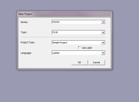
No problem. GX Works 2 would be the software of choice, but both would get the job done. See the screenshot. This is GX Works2 go to File-New, then select your PLC.

Dave

plc's.net.PNG
 
Stick to using standard TON and TOF if you can, and there is no RTO, so you have to make your own (I can send you code).

If you're used to Logix, then it will only take a couple of days for you to learn your way around GX Works 2. I had my first Mitsu project a couple of years ago, and had to start everything from scratch, so if you need help, feel free to ask.

When I created my project it was:
Structured Project
FXCPU
FX3U/FX3UC
Structured Ladder/FBD

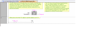
This is a screen from GX Works 2 v1.91, using an FX3U.

TON_GXW2_FX3U.jpg
 
Last edited:
FX3U_Error when using TON instruction

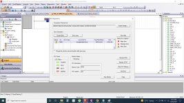
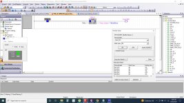
I am being new in GX works 2 need your help in executing TON timer. PLC is FX3U26MR-E. When I download structured ladder program with TON the PLC goes into error. Compiling successfully, runs fine on simulation. Please help
 
Rajan, welcome to the forum.
May I advise you to start a brand-new thread.
You are reviving a post from 2015 which may be related to your topic, but I think it is better you start a new thread with eye-catching and meaningful thread subject.
Also, posting like a screenshot of your logic is really helpful.
 
Last edited:
It would also help to post any other information such as the error code and screenshots of the diagnostics. At a guess you need to be writing any presets (PT) in the correct data type and make sure they are not negative. Is this timer being written to by a HMI or other device?
 
Dear Alfredo, Thank you for welcoming me to the Forum. Its great that Jeev & Parky have replied to my post. Let me continue here...
 
It would also help to post any other information such as the error code and screenshots of the diagnostics. At a guess you need to be writing any presets (PT) in the correct data type and make sure they are not negative. Is this timer being written to by a HMI or other device?

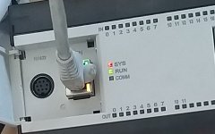
Dear Jeev, Thank you for the reply. Please see the attached screen shots:

PLC_1.jpeg Screenshot_1.jpg Screenshot_2.jpg
 
It would also help to post any other information such as the error code and screenshots of the diagnostics. At a guess you need to be writing any presets (PT) in the correct data type and make sure they are not negative. Is this timer being written to by a HMI or other device?

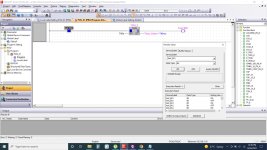
Working fine while on simulation. Here is the screenshot

Screenshot_3.jpg
 

Similar Topics

Hello, I'm new to the design side of "the house I work in" It is necessary for me to import Mitsubishi GXworks2/3 programs into older UNIDRAF7...
Replies
3
Views
918
Hi guys Please I'm working on a project that I need to monitor the flow and I can only allow the process to continues if the measured quantity and...
Replies
4
Views
1,731
Hi guys. I’m working on a project and I want to implement counting at the end of the process but I couldn’t achieve that because of the preset...
Replies
8
Views
3,095
Not very often I ask for help, but this one has got me stumped. There are two ways to indirectly address memory areas in Mitsubishi PLC's. Using...
Replies
15
Views
4,470
Hello, I have connected my Modbus Master simulator to the QCPU and I can see that the QCPU (slave) is writing to numerous registers. For...
Replies
1
Views
1,398
Back
Top Bottom