Best practices for variable linking in Beckhoff/Twincat 3.1

kolyur

Lifetime Supporting Member + Moderator
Join Date
Oct 2004
Location
Wooster, Ohio
Posts
1,602
Can the Beckhoff experts (I know there are a few of you out there) provide some suggestions on the best way to organize links to physical I/O?

I'm in the process of learning Twincat and figuring out variable linking. I know I can drill down through the devices in the I/O section to locate a particular input or output, then link it to a boolean variable. Would it make more sense to link to arrays, e.g. an 8-element BOOL array mapped to an 8-point input module? I'm thinking mainly of projects with high I/O counts where things could get messy real fast. On a similar note, is there any comprehensive way to see the existing links besides clicking on the individual I/O points or modules? It seems like there should be a column I can turn on in the Global Variable list that would show me the links, if any, for each variable--but I can't find any way to do this. What's the best way to keep track of links?
 
you can NOT put them in an array, however you can give them good names in the modulelist.
it is possible to export this list as xml.
and yes it is also available in the global varlist.
if you hover over an existing i/o it will show you the address and the type.
you can also use ___ like machine1_materialpresent etc.
there is a convention page for naming in the helppages.
and it is possible to use a word like machine1.1 to get a BIT, however the names of individual points are not clear then.
you can translate them into type so you can use the type name in your program and at the end use this type to convert to real I/O
like mach[1].materialgone
this is an array like you asked.
 
I have come up with an addressing scheme that makes it fast for linking. This is basically what I use:

NNssB.b

NN = Node number (on Ethernet you have to make up nodes for each rack)
ss = slot number of the card in the rack
B = byte number (for example an analog card would use 0 for first channel, 2 for next)
b = bit number


For instance 01050.0 would tell me to go to rack address 1, slot 5, byte 0, and bit 0

02034 would tell me to go to rack address 2, slot 3, and analog channel 3 (2 bytes for each channel and no bit level)

I create a variable for every IO point and assign an address so I can use that point without re-starting TwinCAT, I simply change the generic name. When it comes to linking, you will find this scheme allows you to very quickly hit a few key strokes in sequence and link all of your variables.

This addressing scheme also works with ARM based controllers.

Many people like to use the wildcard for addressing, such as %I*, but once you do that you cannot rename your variables without breaking links or creating havoc caused by automatic re-addressing.


Here is a quick example:
Code:
VAR_GLOBAL  (* NODE 2 *)
(* Slot 1 (KL1418)  *)
	i20100 AT %IX2010.0 : BOOL;
	i20101 AT %IX2010.1 : BOOL;
	i20102 AT %IX2010.2 : BOOL;
	i20103 AT %IX2010.3 : BOOL;
	i20104 AT %IX2010.4 : BOOL;
	i20105 AT %IX2010.5 : BOOL;
	i20106 AT %IX2010.6 : BOOL;
	i20107 AT %IX2010.7 : BOOL;

(* Slot2 (KL1418) *)
	i20200 AT %IX2020.0 : BOOL;
	i20201 AT %IX2020.1 : BOOL;
	i20202 AT %IX2020.2 : BOOL;
	i20203 AT %IX2020.3 : BOOL;
	i20204 AT %IX2020.4 : BOOL;
	i20205 AT %IX2020.5 : BOOL;
	iCooker24CanTrackFull AT %IX2020.6 : BOOL;
	i20207 AT %IX2020.7 : BOOL;
 
Last edited:
Thanks to both of you, this is great information.

When it comes to linking, you will find this scheme allows you to very quickly hit a few key strokes in sequence and link all of your variables.
Archie, can you elaborate on this? Up until now I've been using the wildcard addresses %I* and %Q*, however I see the logic in applying fixed addresses using your scheme. But how does this make the linking simpler?
 
Archie, can you elaborate on this? Up until now I've been using the wildcard addresses %I* and %Q*, however I see the logic in applying fixed addresses using your scheme. But how does this make the linking simpler?
If you predefine all of your addresses using a scheme that guarantees they are in consecutive order and create an address for every point, they will all link one directly after another.

When you are linking, if you go to the PLC-Configuration and drill to your Input, you double click the first and find the point it goes to. From there on you can double click the next point and hit enter because System Manager will already have the next point selected. This is because System Manager goes to the next available point and since you program addressing would be setup to correspond, you can very quickly go through the list and link the points.

With this method I can link about 50 points in about 20 seconds. It's a little more work up front, but the time is saved in System Manager.

I do a lot of work for a company that adds new input and output devices all the time. It is not easy to stop the line to link a new IO point. If wildcards are used, then you cannot rename your spare variables leaving the program with generic names that are impossible to troubleshoot. By using the method I described above, it solves all of these issues by having all IO prelinked so no system restart is needed when adding a new device. And by not using wildcards, the variables can be renamed without the risk of breaking links.
 
Thank you, this is much clearer to me now. However, I did notice that if I rename a variable with a wildcard address (%I* or %Q*), it does in fact maintain the I/O link--after I do a Build. Under what conditions would this not happen?

I do like using the addressing scheme, if only for the reason that it keeps everything in the right order when you are doing the linking. But I couldn't find much about addressing in the Beckhoff infosys. What exactly is specified by the number you put after %QX, for example? Twincat will let me enter a value between 0 and 128000. Is this directly addressing memory in the controller? Are there different areas for different memory types (i.e. is %QX10 different than %IX10)? If I put addresses for my I/O variables, is it still OK to omit them for internal variables or is there a chance of memory conflicts?

Sorry for what I'm sure are basic questions but I can't find this stuff written anywhere. Thanks again for your help.
 
the I and the Q are real outputs direct on the PLC, markers are in memory, obvious these are specific for the type of plc used.
 
What exactly is specified by the number you put after %QX, for example? Twincat will let me enter a value between 0 and 128000. Is this directly addressing memory in the controller? Are there different areas for different memory types (i.e. is %QX10 different than %IX10)? If I put addresses for my I/O variables, is it still OK to omit them for internal variables or is there a chance of memory conflicts?

%I - Physical Input
%Q - Physical Output
%M - Internal memory

3rd character position

X - Boolean
B - Byte
W - Word
D - Double Word


The I and Q memory are in different areas, so %IX1.0 does not conflict with %QX1.0

Do pay close attention to the fact that the addresses specify BYTE position. So %QW0 and %QW1 will overlap by one byte.

After you build the project it is good to perform a Memory Overlap check.
 
I have come up with an addressing scheme that makes it fast for linking. This is basically what I use:

NNssB.b

NN = Node number (on Ethernet you have to make up nodes for each rack)
ss = slot number of the card in the rack
B = byte number (for example an analog card would use 0 for first channel, 2 for next)
b = bit number


For instance 01050.0 would tell me to go to rack address 1, slot 5, byte 0, and bit 0

02034 would tell me to go to rack address 2, slot 3, and analog channel 3 (2 bytes for each channel and no bit level)

I create a variable for every IO point and assign an address so I can use that point without re-starting TwinCAT, I simply change the generic name. When it comes to linking, you will find this scheme allows you to very quickly hit a few key strokes in sequence and link all of your variables.

This addressing scheme also works with ARM based controllers.

Many people like to use the wildcard for addressing, such as %I*, but once you do that you cannot rename your variables without breaking links or creating havoc caused by automatic re-addressing.


Here is a quick example:
Code:
VAR_GLOBAL  (* NODE 2 *)
(* Slot 1 (KL1418)  *)
    i20100 AT %IX2010.0 : BOOL;
    i20101 AT %IX2010.1 : BOOL;
    i20102 AT %IX2010.2 : BOOL;
    i20103 AT %IX2010.3 : BOOL;
    i20104 AT %IX2010.4 : BOOL;
    i20105 AT %IX2010.5 : BOOL;
    i20106 AT %IX2010.6 : BOOL;
    i20107 AT %IX2010.7 : BOOL;

(* Slot2 (KL1418) *)
    i20200 AT %IX2020.0 : BOOL;
    i20201 AT %IX2020.1 : BOOL;
    i20202 AT %IX2020.2 : BOOL;
    i20203 AT %IX2020.3 : BOOL;
    i20204 AT %IX2020.4 : BOOL;
    i20205 AT %IX2020.5 : BOOL;
    iCooker24CanTrackFull AT %IX2020.6 : BOOL;
    i20207 AT %IX2020.7 : BOOL;


Archie,

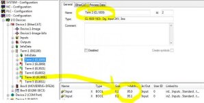
what do you do in a situation like this (see attachment 'Beckhoff1')?

I have added some special hardware and then the adresses start to shift automatically.

I am using a CX but the same thing happens with a BC.

That's the reason why you need to link, at least that's what they have told me.


Look what happens to the adresses when I insert an analog card afterwards (see attachment 'Beckhoff2').

beckhoff1.jpg beckhoff2.jpg
 
Archie,

what do you do in a situation like this (see attachment 'Beckhoff1')?

I have added some special hardware and then the adresses start to shift automatically.

I am using a CX but the same thing happens with a BC.

That's the reason why you need to link, at least that's what they have told me.


Look what happens to the adresses when I insert an analog card afterwards (see attachment 'Beckhoff2').
The addressing follows the same scheme, As for the EL67xx card, it will "spawn" off additional nodes.

In my example the first EK1100 I specify as Node 1. What comes off EL67xx can then be node 2,3,4 etc. In your example you are using an Ethernet/IP which could have any type of hardware and not necessarily slot based IO, so the "slot" digits could represent something other than a slot. For example, the next device could be consider node 2 and use an address like %IX2010.0

It does not matter what the EL67xx does to its internal addresses because the addresses you create will always stay the same.

AddressDemo.jpg
 
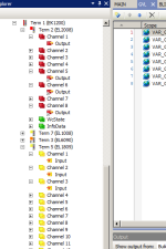
Archie, how is it that your I/O points are shown in a continuous list for each module? In mine I have to drill down into a Channel for each point--kind of messy. Is there a setting for that or is it a Twincat 2 vs 3 thing?

beckhoff_io.png
 
Archie, how is it that your I/O points are shown in a continuous list for each module? In mine I have to drill down into a Channel for each point--kind of messy. Is there a setting for that or is it a Twincat 2 vs 3 thing?
I manually name terminals when adding or rename everything if I scan them in. On a large system it can be tedious, but I like well organized descriptions that also follow the patterns of my addressing scheme.
 
I did notice that if I rename a variable with a wildcard address (%I* or %Q*), it does in fact maintain the I/O link--after I do a Build. Under what conditions would this not happen?
Here is a scenario in which I accidentally took down half a plant with.

I was given a small window of time to shut everything down and add some IO points to a fairly large system. That program had a mix of wildcards and fixed addresses. I added some additional fixed addresses that happened to be higher than the auto generated addresses for the wild cards. TwinCAT regenerated and changed all of the auto generated addresses. I linked the new IO and restarted the system. As we tried to restart the system a large portion of the IO no longer worked. After a bit of time digging through, I discovered that re-addressing also deleted the links to all of those points.
 
Here is a scenario in which I accidentally took down half a plant with.

OK you've sufficiently scared me... this is the kind of stuff that keeps me up at night. I like your addressing scheme and will stick to it. My coworker went to Beckhoff training and they only taught the wildcard method, so I'll have to educate him also. Thank you!

:site:
 

Similar Topics

Hi everyone. I am very new to TIA Portal, and I come mostly from the Rockwell world. I have a question regarding program structure. For some...
Replies
10
Views
3,532
I have a relatively small network but I am having some issues with PowerFlex 755 drives (using the native ethernet card) Faulting with the F926...
Replies
0
Views
214
What's the best way to use lots of MSG instructions in the same program? Both multiple messages with the same device, and other devices. I've read...
Replies
10
Views
1,171
Hi all, We are looking for the best practices when it comes to maintenance technicians having online access to our PLC's. We would like to give...
Replies
5
Views
1,146
I would like to compile a list of all the CX-Programmer PID Best Practices If there is some clever way you have figured out to do something and...
Replies
0
Views
673
Back
Top Bottom