Sy3220-5l

arran

Member
Join Date
Sep 2015
Location
UK
Posts
53
Hi,

I have this device :

productpic


I have a look on the internet, but was unable to obtain any information about the connectivity of the wires. Can anyone guide me or assist me in telling me what the wires needs to be connected to. Both sides of the device have a 24VDC so I think it will link to a supply, but than how do I control the values.

Please any help me.

Thank You
 
This looks to be a SMC valve.

http://www.smcpneumatics.com/pdfs/SY.New.pdf

What are you connecting to the valve?

Garry
http://www.accautomation.ca


The is from SMC. At the moment I'm not fully sure how's it going to be connected but it will be used in a dispensing project of mine. The equipment I have are Adam-4024module (already setup to send and receive voltage/current values) , ITV2030-312BS3 (SMC) used to regulate the pressure and the pipes would be connected to the SY3220-5L and something else (at the moment not sure as I just started this) . I also have a
CDUK16-200 (SMC) but I'm not fully sure about this as well.

Any help appreciated

Thank you
 
There is plenty of information on SMC web site. This is a 2-position double-solenoid valve; when coil A is energized, the pressure input is switched to port A and stays that way even when coil A is de-energized. Port B operates the same way when coil B is energized. Energizing both coils is not a normal option and should be avoided although I beleive the valve spool will stay in the last state if that happens.

Suffix "-5" indicates these are 24VDC coils. for each coil, the red wire is positive and the black wire is negative.

When you said energized, you mean when a voltage pulse or just voltage is sent. Or you mean something else. I said that because the device needs a power source for both sides but than how do I control it with air pressure?
That's the bit I'm confused about.

I did have a look online, but all that I kind of found was how to assembly the device and it used tables with data and I didn't quite understand that. I need something in writing where I'm able to know what there talking about. I'm new to this so I need to know the basic.

Thank You
 
Last edited:
When you said energized, you mean when a voltage pulse or just voltage is sent.
When I say "energized", that means "connect the red wire to a +24VDC source and the black wire to -24VDC". It may take the valve about 100 - 200 milliseconds to actually switch, after which you can disconnect the coil if you want. Or you can keep it energized until you need to switch the valve back. Which you do by de-energizing this coil and energizing (that is, applying the voltage) to another coil.

Now, for the valve to actally switch, the "P" port must be connected to a compressed air source. The solenoids do not actually move the spool inside the valve; they switch a tiny valve inside (called a pilot valve) which in turn moves the spool by swicthing the compressed air.

Ok.
To energized I supply +24 and -24 VDC and to de-energize I stop supplying this and supply +24 and -24 VDC to the other side. So this means if I need to control the values depending on a condition they cannot be connected directly to the power supply. Is it possible that I can supply +/- 10VDC instead of the +/- 24VDC as I don't have the power supply for -24VDC and plus the only way I can control them is by using the ADAM-4024 module which is capable to supplying +/-10VDC.

For the device SY3220-5L, would you able to please provide a link to a site, where it talks about EA,EB,A and B for the device and how the connections would send the air pressure one way and another. Something that is at beginner level. For example: If I were to connect the EA and EB together using
2-Pcs-3-Way-T-shaped-8mm-4mm-OD-Tube-Tee-Push-In-Pneumatic-Connector-Plastic.jpg

to effectively produce one link to both of them and I only used A and not B. Then how do I know which side of the device terminal would supply would send the pressure through A and which would stop it.

Thank you for the help
 
Last edited:
Not sure how / why you're using the Adam-4024 since it appears to be outputting 0-20 mA or 4-20 mA or +- 10 VDC analog.

What do expect or need to valve to actually do because the one you have is basically either switched fully one way or the other?

The valve nomenclature is :
P = Pressure port - supply pressure goes into the valve here
A = One of the 'cylinder' ports - working pressure comes out here when you energize the A solenoid (or B - depends on the valve)
B = The other 'cylinder' port - pressure comes out this port when it's not coming out the A port
EA = The exhaust port for the A port (you gotta get pressure back out of the cylinder somehow)
EB = (see EA description).

You could connect EA and EB together but most times people do not.
If you are unsure which port and solenoid coil are related, turn the pressure down on your regulator and energize one or the other coil and see.
It's perfectly valid to plug the B port if you don't need it but he cylinder you say you have is double acting which implies that you will connect BOTH A and B ports to the cylinder (one for each direction).

Maybe a description of what you're trying to accomplish will help reduce a cat-and-mouse conversation where more questions are raised than answered.
 
Not sure how / why you're using the Adam-4024 since it appears to be outputting 0-20 mA or 4-20 mA or +- 10 VDC analog. .

I have just been given this project to me, which involves using the following equipment SY3220-5L (SMC), ITV2030-312BS3 (SMC), Adam-4024 (using Adam-4520 as a converter) and CDUK16-200 (SMC). This project is for dispensing liquids. At the moment, I'm just getting to understand how everything is coming together. At the moment, I have coded the Adam module, so I can set/read voltage values at each terminals. The rest I'm trying to figure out. With the knowledge gained so far I believe that Adam-4024 will be used for ITV2030-312BS3. To send 0 to +10VDC ad read values using the output terminal. Not sure what happens when the voltage will be applied. Maybe you give me some information about this? I think higher voltage means pressure increases from minimum to maximum quickly on ITV2030-312BS3 .


What do expect or need to valve to actually do because the one you have is basically either switched fully one way or the other?
I need to control the values so that depending on what the condition is e.g.: the liquid reaches a certain weight, I need to be able to use that information and turn the value off. Since I'm only dispensing using one A or B, that would mean I will not be using the other. Now this brings me to the other question, that the supply terminals for SY3220-5L cannot be connected to the power supply, as I need to be able to control turning off and on for the values. I'm I right to say this? If yes than this means I need a supply source that I can send control or do I use the values to control? hmm not sure about this. Could you please clarify this for me.

About the CDUK16-200 component not sure how it will play its part in my project.

Hope this has clarified what my main goal is.

Thank you for the help
 
Most dispensing application that I have seen use variable pressure to try to push the fluid - thick viscous fluids need higher pressure than thin fluids. That is usually set and forgotten using a pressure regulator.
Then, there is a dispensing valve that opens to let the fluid flow. Sometimes this is a cylinder pinching off a hose.

So, you have :
an analog output device
a proportional pressure regulator
a directional valve
a cylinder

You were handed a bag of components and told to create a thing without being told the intended purpose of these components?

As a controls engineer, I am handed a project but it includes a hookup diagram / schematics so I can tell how it goes together, but it's generally not including a statement "here's stuff, figure it out". The decision on what components to obtain was based on some intelligence that helps to ensure that everything will work together and have a purpose in the final solution.
 
With the knowledge gained so far I believe that Adam-4024 will be used for ITV2030-312BS3. To send 0 to +10VDC ad read values using the output terminal. Not sure what happens when the voltage will be applied. Maybe you give me some information about this? I think higher voltage means pressure increases from minimum to maximum quickly on ITV2030-312BS3 .

With the analog regulator you have, generally higher output voltage will equal higher pressure.

I need to control the values so that depending on what the condition is e.g.: the liquid reaches a certain weight, I need to be able to use that information and turn the value off. Since I'm only dispensing using one A or B, that would mean I will not be using the other.
Many valves are not suitable for many liquids. Types of seals, etc., would determine this.
Your valve seems more suitable for moving the cylinder around - extend and retract. And since it's a double solenoid valve, no you cannot just ignore the other solenoid. If you energize solenoid A, the valve will shift and you will have to energize solenoid B to shift it to the previous position.
A single solenoid 2-way valve would be a better choice since it offers on/off (flow/no flow) and no exhaust.
But, then, I am unsure if the valve is for dispensing or actuating the cylinder (in which case it is probably the correct choice).

Now this brings me to the other question, that the supply terminals for SY3220-5L cannot be connected to the power supply, as I need to be able to control turning off and on for the values. I'm I right to say this? If yes than this means I need a supply source that I can send control or do I use the values to control? hmm not sure about this. Could you please clarify this for me.
You will likely need to use some kind of controller with I/O to turn the valve on/off AND a 24 VDC power supply to provide power to the outputs.

You used the word 'value' several times in your post - is this a typo? did you mean 'valve' in most all cases?
 
It's true that I was given no schematic/drawing of how the components are supports to go together, but there's a maintenance on the robots at one point hope to ask if I can have a look inside the robot to maybe have a better idea. I know this is a bit weird, even I didn't expect this, where I just handed some components/devices and said do make a dispensing system. I really appreciate your help for this.


With the analog regulator you have, generally higher output voltage will equal higher pressure.
This means that when I set the min/max pressure on the ITV2030-312BS3, supplying 0VDC will equal min pressure and +10VDC would mean max pressure from the device. Am I right to say this?


Many valves are not suitable for many liquids. Types of seals, etc., would determine this.
Your valve seems more suitable for moving the cylinder around - extend and retract. And since it's a double solenoid valve, no you cannot just ignore the other solenoid. If you energize solenoid A, the valve will shift and you will have to energize solenoid B to shift it to the previous position.
A single solenoid 2-way valve would be a better choice since it offers on/off (flow/no flow) and no exhaust.
But, then, I am unsure if the valve is for dispensing or actuating the cylinder (in which case it is probably the correct choice).
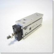
What my boss wants to do is actually do both of them, so dispense and actuating the cylinder, but for starting this off as you say it's more suitable for
actuating the cylinder, so I will pick this option. So what I have done is connected both valves A and B to the two holes at the side of the CDUK16-200. The image is shown below: I'm sure I did this right?
thumbnail.php


You will likely need to use some kind of controller with I/O to turn the valve on/off AND a 24 VDC power supply to provide power to the outputs.
So I need a I/O controller that is capable of outputting 24DVC, so that I can control the controller to supply that voltage or not to supply that voltage to the SY3220-5L. Is this Correct, could you please confirm this? Also, can I not just use Adam module +10VDC to control this. If not do you have any suggestions of a controller I/O.

Someone in this form mentioned about using +24VDC for red and -24VDC to control the SY3220-5L. What your opinion about this? I not saying he's wrong but he maybe mistakenly wrote -24VDC instead of ground. I spoke about this to my boss and he's not quite sure about me using that? I though black would be linked to ground and red to +24VDC. Also, on the internet it doesn't mention about -24VDC. Could you clarify this for me please

You used the word 'value' several times in your post - is this a typo? did you mean 'valve' in most all cases?
Yes that was my mistake, it was suppose to be valve, thanks for picking that up.

Thank you for the help you have given me, it's starting to make so much sense now.
Also like to thank you in advance for future help
 
This means that when I set the min/max pressure on the ITV2030-312BS3, supplying 0VDC will equal min pressure and +10VDC would mean max pressure from the device. Am I right to say this?
I believe that would be correct although I have not thoroughly researched your components. And the max pressure would be set on the regulator that feeds the device.

So what I have done is connected both valves A and B to the two holes at the side of the CDUK16-200. ... I'm sure I did this right?
Yes, if you intend to control the cylinder with the valve you have, you would connect as described.

So I need a I/O controller that is capable of outputting 24DVC, so that I can control the controller to supply that voltage or not to supply that voltage to the SY3220-5L. Is this Correct, could you please confirm this?
Yes, I believe that's what I said.

Also, can I not just use Adam module +10VDC to control this. If not do you have any suggestions of a controller I/O.
It appears that Adam module has 4 digital inputs but that version has no digital outputs to control 24 VDC. The model ADAM-4022T appears to have 2 digital inputs and 2 digital outputs for 10 to 30 VDC.

Someone in this form mentioned about using +24VDC for red and -24VDC to control the SY3220-5L. What your opinion about this? I not saying he's wrong but he maybe mistakenly wrote -24VDC instead of ground. I spoke about this to my boss and he's not quite sure about me using that? I though black would be linked to ground and red to +24VDC. Also, on the internet it doesn't mention about -24VDC. Could you clarify this for me please
Yes, you are correct - +24 and 0 VDC.
 
:geek: Thank you for the help you have provided me. I really appreciate it.

I will take your advice and ask my boss for ordering the extra module.

However, before I do that I had a look into the 4024 module and I see that here http://www.bb-elec.com/Products/Manuals/ADAM-4000_manual_V17_8122011.pdf on page 72 and 73 , the digital pin I think is capable of being varied +10~30 VDC? Not sure but maybe it's possible for +24VDC ?

On page 73 the isolation input diagram, I understand IDIx is digital output terminal of Adam-4024, but do you what COM means.


Thank you for the help
 
Last edited:
COM = common. The diagram you mentioned is for the 4024 module which supposedly has no outputs. The 4022T has 2 digital inputs and 2 digital outputs.

The inputs and outputs are very flexible - you can supply anywhere from 10 to 30 VDC to the inputs to trigger them. 24 VDC would fall under that range.
The outputs are transistor open-collector meaning they supply no power - you do. And you connect to them, well, here's a link to some open collector circuits:
http://www.homecontrols.com/homecontrols/content/Blog/OpenCollectorDoc.pdf

I suggest you contact Advantech or whomever you got the original module from to discuss the 4022T to determine if it will meet your needs.
http://www2.advantech.com/products/...mod_e37e5d1e-4d4f-4efa-b436-0975fd7125ce.aspx
 
Back
Top Bottom