[Help please] Temperature control with seconde thermocouple as security

MAIDEL

Member
Join Date
Feb 2011
Location
France
Posts
19
Hello everyone,

We have an application in TIA Portal (with ET200SP) to manage the furnace temperature control according to an operator setpoint. For this we have a type K thermocouple to measure the temperature inside the furnace (about 1050 ° C). One importante Thing, a second thermocouple is here to control the temperature of the insulation of the furnace which must not at any time exceed 1080 ° C. For this we opt for a cascade control but I would like to know if this will be enough to have no problem and avoid any overshoot that would have exceeded 1080 ° C at the temperature of the insulation.

I am not an expert in control but I have some issues, including the cascade control, I want to put competent people in the field.

If you know another another method for my application thank you enlighten me on this.

Thanks for your help.
 
It is "good practice" and regulatory code that the furnace be protected by a separate safety control circuit, which interrupts the flow of energy when temperature exceeds the designated setpoint, 1050 C in this case.

In the USA, the code says that the safety circuit must have its own sensor and controller/logic solver. The commercial products are derivatives of standard temperature controllers with a control relay that latches when tripped, requiring a manual reset. Digital communications like Modbus, is limited to read-only functions.

The control output relay is wired in series with the safety shutdown gas valve or a shunt trip circuit breaker for electric heat.

The safety is not a cascade loop, an alarm or a second control circuit in the primary temperature controller/PLC. It is a separate 'limit' controller with its own sensor.

Hi,

Thanks for your reply,

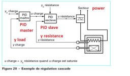
I don't know if I have correctly explained the process, here attached a picture (sorry it's in french, I put translation in red)

We have a thermocouple for temperature control inside the furnace and another thermocouple for the insulation of the furnace (in the picture it is shown "resistance", this is the insulation which does not exceed 1080 ° C.

Regarding your suggestion, I fear temperature inertia problems, for example if my furnace seeks to reach 1050 ° C (ie PID output between 0 and 100%) and my measure of insulation temperature crosses 1080 °C even by cutting the output of the PID, the temperature will exceed 1080 ° C because of the inertia.

Sorry for my bad english

cascade.jpg
 
Yes, using cascade control for 2 thermocouples is a correct way to run the furnace while limiting wall insulation temperatures.

AND DanW is correct that a third thermocouple should be in the furnace to be a high-limit shutdown if a problem happens. The high limit shut down is totally independent, so it can not use either of the controlling thermocouples.

But hwo it works ? How can cascade control avoid overshooting.
Could you explain why a 0-100% signal from the master loop output can be connected to the Setpoint input of the slave loop ? What about the inertie in cascade loop is there no problem with inertia ?

If I understand well, before I connect the output of the master to the SP input of the slave, I have to convert the 0% signal(from master loop output) to 0 °C for the SP input of the slave and convert the 100% signal(from master loop output) to 1080 °C for the SP input of the slave ??(as I said 1080 °C is for the insulator of the furnace, it's not allowed to get through this threshold)

I ask this question because in many documents we see direct link between master loop output and slave loop SP input

Thanks in advance

You cannot connect the 0-100% signal directly to the SP of the Furnace Temp Loop - you must convert the 0-100% to ºC within an acceptable range for the Furnace Temp.

However, I would suggest that you might want to consider another control option. That would be to break the loops apart, set the Insulation SP to something less than 1080 ºC and set the Furnace SP to the actual Furnace SP desired. Then use a Low Select between the two control outputs and drive the temperature with it.

The reason I suggest this is that it should give you better control of the Furnace Temp while preventing overshoot to the Insulation. As long as the Insulation Temp is below the Setpoint, you will have full range control of the Furnace Temp.

Another option would be to make the Furnace Loop provide the SP to the Insulation Loop with the 0-100% output ranged to something like 1000ºC to 1080ºC (or less if overshoot is a real possibility). In a balanced system, this will allow you to control the Furnace Temp to the SP you desire, while keeping the Insulation Temp within acceptable range. The Insulation Temp is only driven as high as necessary to maintain the desired Furnace Temp while the range you choose for the 0-100% conversion will prevent the Insulation from overheating. The original scheme does not allow for actual control of a particular Furnace Temperature (it is always dependent on the Insulation Temp) - both of my options do allow you to maintain the Furnace Temperature at the desired SP.

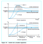
Another company has already make this working with cascade control, they make this for my customer (with stand alone controller not with PLC), and they were very satisfied with the result (you can see my attached picture to compare mono loop and twin loop)

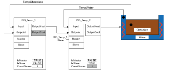
Now I have a Siemens PLC (ET200SP) and I try to use the PID_temp block to make the cascade control possible but I don't how to make the safety control of the insulation temperature with this block, see my attached picture.

difference beteen mono loop and twin loop.png siemens pid_temp casscade control example.png
 
Another company has already make this working with cascade control, they make this for my customer (with stand alone controller not with PLC), and they were very satisfied with the result (you can see my attached picture to compare mono loop and twin loop)

Now I have a Siemens PLC (ET200SP) and I try to use the PID_temp block to make the cascade control possible but I don't how to make the safety control of the insulation temperature with this block, see my attached picture.

The trends don't tell us which control scheme the other company used, only that it supposedly worked. I've done this type of control with multi-loop controllers and PLCs using both options I suggested. I've never used your original scheme because it won't provide a stable Furnace Temperature.

I don't program Siemens PLCs so I'll back out of the discussion.
 
Load power to the heating elements should be capable of being disconnected, should an over-temp situation occur. This should not be part of PLC control, it should be stand-alone, has been my experience (typical of any E-stop circuit). Also, if you have volatile process gases flowing, they should have dead-man valves that are shut (in most cases) whenever any sort of emergency style event (eg...furnace over-temp).
 
The trends don't tell us which control scheme the other company used, only that it supposedly worked. I've done this type of control with multi-loop controllers and PLCs using both options I suggested. I've never used your original scheme because it won't provide a stable Furnace Temperature.

I don't program Siemens PLCs so I'll back out of the discussion.

Thanks a lot for your suggestion, It's not lost for future. Maybe I will use it in another application. Thanks for sharing your experience JHarbin

Load power to the heating elements should be capable of being disconnected, should an over-temp situation occur. This should not be part of PLC control, it should be stand-alone, has been my experience (typical of any E-stop circuit). Also, if you have volatile process gases flowing, they should have dead-man valves that are shut (in most cases) whenever any sort of emergency style event (eg...furnace over-temp).

You're right, it will be more safe to add a third thermocouple with my cascade control.


Anyone has an experience with Siemens PLC and cascade control ?
 
It does look like cascade control to me. We did something like this (many, many years ago) with a 2 loop, stand alone PID temperature controller. The application was similar. Control the load while keeping the external wall temperature below a value. Once you auto-tuned it, it worked perfectly.
 
[..] keeping the external wall temperature below a value[..].

Good, where did you put this value, did you only made a 0=>100% conversion (output of the master loop) to a 0=>1000°C (SP input of the slave loop)???, (with 1000°C represent the value you talked about)

I know it's been a long long long time, thanks in any case
 

Similar Topics

Dear colleagues, I am very new to industrial and now I am trying to fix the plastic injection machine. On terminal display, 5 sensors outputs show...
Replies
3
Views
1,763
Hello, I am trying to get a Yokogawa Hart pressure Transmitter and a Rosemount Temp Transmitter to read on a 1769-IF4 module on an L33ERM...
Replies
10
Views
376
Please help me, I have solve many week but still not solve it. I found trouble of factory talk studio when I set tag by browse address of OPC...
Replies
0
Views
117
Hello Everyone, i Have im my Industry a Endress & Hauser Promag400 this has a screen that constantly have that error, it says to wait, somebody...
Replies
2
Views
475
Back
Top Bottom