Way OT: UL508A SB and branch circuit protection

kamenges

Member
Join Date
Nov 2002
Location
Green Bay, WI
Posts
4,332
I generally design around using current limiting fuses in all the power circuits in the control panels I design. However, a recent customer asked that we use circuit breakers instead of fuses. The one concession was that we could use a Class J fuse at the disconnect, which then became the circuit feeder fuse.

The problem I ran into when calculating short circuit current rating (SCCR) for the enclosure was with the branch circuit breakers. According to UL508A supplement B 4.3.3(b), I need to use the lowest interrupt rating of the branch circuit overcurrent protection devices as the SCCR for the enclosure. This is in spite of the fact that the peak let-through current of the feeder Class J fuse is much less than the branch circuit protection interrupt rating at the available fault current at the plant. So instead of being able to rate the enclosure at 65kA SCCR and be well over the available fault current I need to rate it at 10kA, which is less than the available fault current.

Can anyone give me anything approaching a reasonable design rationale why branch circuit protection devices are treated differently than other components relative to the feeders fuses current limiting capability? It doesn't make sense to me. Either the current limiting fuse limits the current to stated levels or it doesn't. If it does then why can't I use that capability relative to the interrupt rating of another fuse or circuit breaker downstream of it?

Keith
 
It may not actually be that way, depending on WHAT the down stream devices are and how they are configured.

The thing is, the use of the Current Limiting Fuse allows for the use of non-interrupting power circuit devices below the fuse, such as a contactor or overload relay, that have an SCCR lower than the available fault current, but above the fuse let through. But if there is another Branch Circuit Protection device, like a circuit breaker, then the CL Fuse does NOT change the IC of that circuit breaker.

So for example:
65kA AFC

100A CL Fuse, 200kAIC, 4kA let through
|
V

25kAIC rated breaker
|
V

Contactor rated 10kA SCCR
|
V
OL Relay rated 5kA SCCR

Overall panel SCCR = 25kAIC, because the lowest rated BRANCH device is 25kAIC, but the low let through of the CL Fuse allowed for the use of the 5kA OL relay.

But here's the thing. If you bought the breaker, contactor and overload relay from the SAME manufacturer, and that mfr tested then TOGETHER as a listed combination of devices at 65kA SCCR even though the breaker by itself is only 25kAIC, then the entire panel could get a listing at 65kA SCCR (even without the fuse by the way). Many, if not MOST, of the major control equipment manufacturers have done this for THEIR OWN components, because it's necessary for them to stay in business. But almost nobody has tested THEIR motor starters or controllers with ANOTHER brand of breaker (or if they don't have their own breakers, then they have tested them with ONLY ONE). That's because EACH SPECIFIC combination of devices must be tested, and it's very expensive.

Where this all bites you is when you have distribution breakers in your panel that are all alone feeding something outside of the panel, i.e. not part of a "listed combination" such as a motor starter package. In that case, the breakers themselves must match the available fault current, no way around it.
 
I understand how to determine an enclosure SCCR as well as the usefulness of combination ratings and high fault current ratings. That isn't the issue.

The question is, given the example jraef shows, what is the engineering rationale behind a 25k enclosure SCCR even though the feeder fuse let-through is 4kA peak, well under the 25kA rating of the branch circuit protection? And just for those keeping score at home, "Because UL says so" is not a valid engineering rationale, although is is the reality of the situation.

Keith
 
Because BOTH devices are interrupting devices, and you cannot guarantee which one will react first. Its highly LIKELY that the fuse will clear first and limit the current, but not ABSOLUTE. So if there is a fault down stream of the breaker, and the BREAKER begins to release first, the fault current seen by that breaker before the fuse clears it may be closer to the AFC. If its only rated for 25kA and the fault current gets to 40kA it could explode. The other devices are not going to be interrupting the fault current, only SEEING it, so they can wait for the interrupting device and just have to withstand the forces involved.

I'm not saying it WILL happen that way, I'm saying it MIGHT, so UL is erring on the side of caution. This is the way they explained it to me in the UL508A class I attended when becoming a listed shop.
 
Originally posted by jraef:

So if there is a fault down stream of the breaker, and the BREAKER begins to release first, the fault current seen by that breaker before the fuse clears it may be closer to the AFC.

And that is where I lose understanding. It doesn't matter which reacts first, although you would expect the feeder fuse to react first all things being equal. If you are using a currently limiting circuit protection device you should never see a peak current downstream of the current limiting device that is above the listed peak let-through current. If you do then the current limiting circuit protection device is not limiting the current to its published value. UL can't have it both ways...well, OK, they can. They are UL and they make the rules. But it is unreasonable to say in one breath that a given current limiting circuit protection device will limit the peak let-through current to, for example, 10kA given a specific available fault current but then in the next breath to say that a device rated to 25kA cannot be guaranteed to survive downstream of that same device. Either it is current limiting to the specified level or it is not. It can't be both.

Keith

Keith
 
It doesn't look like UL lets you use the manufacturer let-through curves for current-limiting fuses, only for current-limiting breakers. You have to use UL 508A table SB4.2 to determine the Umbrella limit for the fuse. So in jraef's example, a 100A J-Class fuse rated at 200KA with 65kA AFC would have a peak let-through (I^2 t x 10^3) of 80 kA, not 4.

At least, that's what I gather from Bussmann's document on it.
 
Originally posted by FactoryTalktotheHand:

So in jraef's example, a 100A J-Class fuse rated at 200KA with 65kA AFC would have a peak let-through (I^2 t x 10^3) of 80 kA, not 4.

You are looking at the peak let-through energy column, not the peak let-through current column. Peak let-though energy comes into play if you want to use a different class of current protection as a replacement. In your example, since there is no 65kA AFC column you would need to use the 100kA column, resulting in a 14kA peak let-through.

I would be OK if I were allowed to use the table values in SB. That isn't my argument. My argument is I can't use the current limiting capability at all where other overcurrent protection devices are concerned for no engineering reason that I can discern. The point was brought up by jraef already that UL believes a dangerous condition could occur if the branch protection device starts to clear before the feeder device clears. i just can't see where the danger would come from if you trust the current limiting capability of the feeder fuse.

Keith

That makes sense. I just found this document online from Littelfuse: http://www.ttiinc.com/object/wp_littelfuse_using_fuses_increase_sccr.html

Their example has the limiting factor of a distribution block rated at 10kA, but if protected by a Class J Current-Limiting fuse, they're saying you could, in fact, rate it higher:

"Therefore, if tested and Listed by a NRTL, the SCCR of
this panel could be 60,000 Amperes or more when using
60 Ampere Littelfuse JTD_ID Class J fuses. In fact, if the
prospective available symmetrical RMS fault current were
200 kA, the fuses would limit the apparent RMS fault current
to only 4000 Amperes, safely protecting all components
within the panel."

The phrasing here is "tested." I'm not sure if this means you would have to get the entire panel assembly tested by UL or some other NRTL, or if the test results of the listed components inside will suffice. It also says:

"UL 508A Supplement SB currently does not utilize the
apparent RMS let-through current of current-limiting over
current protective devices to establish the SCCR of industrial
control panels. "

So, I guess I have the same question you do: "why?"
 
Last edited:
The question is, given the example jraef shows, what is the engineering rationale behind a 25k enclosure SCCR even though the feeder fuse let-through is 4kA peak, well under the 25kA rating of the branch circuit protection?
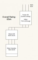
The rationale is that on a labelled current limiting device, the 25kA rating is the maximum it can withstand without being dangerous when it clears a fault. But, because it's constructed in a way that it will only let through 4kA, it then becomes allowable for downstream non-protective devices to only have to meet the 4kA rating.

2015-10-23_7-06-13.jpg
 
Example 2: Using a current-limiting feeder, as long as any non-protective devices meet the let-through, you can use the SCCR of the feeder.

EDIT: Sorry for the individual posts. It was the quickest way to display all the pics.

limiting.jpg
 
That makes sense. I did some more thinking. As I posted above, if you're using a Current-limiting breaker, you can use the manufacturer's peak let-through. If you're using a Current-limiting fuse, you need to use table SB4.2.

For example. I have a panel with a 400-amp feed, with the feeder protected by current-limiting 400A fuses. My limiting factor is a 10kA SCCR power distribution block. According to Table SB4.2, my let-through Ip at 400A with up to 50kA AFC is 25kA. Since 25kA > 10kA, I have to rate the panel at 10kA. If my panel had only a 60-amp feed, the Ip would only be 8kA, which would mean I could rate my panel at 200kA, since 8kA < 10kA so the distribution block would be adequately protected.

Personally, I think the rationale behind it is the same reason when you're calculating Panel FLA you have to use the NEC chart instead of the manufacturer nameplate: fuses are changeable items. If you want to bump up your panel to 200kA by putting a current-limiting "wonderfuse" on the feeder, that could all be for naught because someone could come along in a few years and replace it with a lower SCCR fuse and now the panel rating is no longer accurate. A breaker isn't designed to be changed routinely so that is probably why UL lets you use the manufacturer let-through curves in that case.
 
Keep in mind that Let-through is only for branch components. If the distribution block is in the feeder circuit, then you still have to use the SCCR of the block. Meaning you would need a 25kA block. Or in the example below, a 65kA block.

block.jpg
 
Last edited:
Originally posted by JordanCClark:

...as long as any non-protective devices meet the let-through,...

This phrase is the issue. What engineering rationale is used to say that peak let-through can be used as the fault current comparison when using non-protective device but is can't be used when talking about protective devices? I don't see where the distinction comes from.

Keith
 

Similar Topics

We are considering dropping our UL membership because most of our customers do not care if we are a 508A shop. However, there may be times when a...
Replies
8
Views
396
Is there anyone that can give me the run-down on differences that are required for control panels sold in European markets, compared to those for...
Replies
3
Views
739
Anybody have a recent experience becoming a UL508A panel shop? If so, how long did it take from initial contact to being able to apply stickers...
Replies
3
Views
1,232
Hello, do 3 PH AC Servo Motors ( 1S Omron) follow the same rules as regular AC servo Motors? can I use Table 50.1 (UL508) to calculate FLC of...
Replies
4
Views
2,037
  • Poll
Luckily, I do not have to worry about this test, but I am creating this poll for atc2222.
Replies
36
Views
40,481
Back
Top Bottom