Still kind of confused

jaywillnot

Lifetime Supporting Member
Join Date
Apr 2015
Location
Alabama
Posts
69
Okay, I understand the whole "the last rung wins" concept, and by gosh, I'm really trying to learn to apply it with programming practice but sometimes I still get confused on how to get the outcome I want.

Apparently, I'm still stuck in the A+B=C mode when I should be looking at it as if to get to C from A I need to find where B fits in. I know I'm losing ya'll and I'm sorry, heck I'm losing myself. I know that we must write the program to interact and control the physical relay logic wired into the machine, but how can we have the start/stop conditions on say Rung 20 of File 1 after a lot of other mathematical conditions and it still work correctly?

I've been going over the Bottle Line Ex 5 Lancie wrote and I'm trying to wrap my head around it. Maybe I was taught wrong in college and I wasted my money....👨🏻‍🏫

Its really frustrating when asked to help someone on the floor because they look up to me and I can't help them.
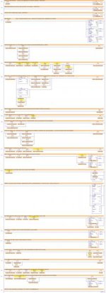
Bottle Line Lancie.jpg
 
Your attached images are too small and when I zoom in they are too blurry. Do you have a specific question?

Classical PLC sequence:

1. Get the status of the physical inputs from the input modules.
2. Execute each rung of ladder logic.
3. Send the results of executing the ladder logic to the output modules.
4. Internal housekeeping, including communications with the HMI if there is one.
5. Go back to Step 1 and do it all again.
 
have you watched the eleven videos on my website? ... especially the one titled: "Video #10 – Which Rung Wins?" ... NOTE: if you've never seen the videos before, do NOT skip ahead to number 10 ... watch them all in number order – it's one continuous lesson – cut up into ten-minute chunks to fit the YouTube format ...

regarding your question:

how can we have the start/stop conditions on say Rung 20 of File 1 after a lot of other mathematical conditions and it still work correctly?

this question makes it sound as though you're thinking (incorrectly) that the stuff at the top of the program comes into play FOR AWHILE (maybe for several seconds or so) and then LATER the stuff further down in the program comes into play ...

that's NOT how the PLC processes its rungs ... in general terms, ALL of the rungs get exercised on one continuous scan cycle ... (about 200 scan cycles per second) ...

this "mental picture" sometimes helps:

don't think of the PLC reading its program rungs like a BOOK page-by-page ...

instead ...

picture that it's reading the entire program like a SCROLL – where the very end of the program is "looped around" – and the bottom end is taped to the very beginning ... in other words, the rungs are read more like a LOOP (picture a conveyor belt) ... that SCROLL gets read all the way through - about 200 times per second ...

if this still doesn't make sense to you – especially after watching the videos (and especially #10) then let us know and we'll try to go further ...

Maybe I was taught wrong in college

that happens all too often ...
 
Last edited:
jaywillnot,

Let's look at it a different way.
You have a program with 250 rungs.

Rung 25 says that a+b=c

Rung 125 says that a+b-q+g = c

rung 150 says that x-y+d=c

rung 225 says that a+b+f+g-d=c

rung 225 wins.

another way to look at it.

this is becoming a more popular way to do ladder logic

you have 4 parts to turning on a plc output.

1. enable something be done (event)
2. you get permission for the event to happen
3. you command the event
4. you turn on the event

take a machine with several operations and you want to go into the automatic cycle.

1. enable - this tells you if its ok to start the auto cycle. air pressure ok, power ok, machine components at home, are you in automatic mode?
2 if yes - you have permission.
3. press the auto cycle start button.
4. the autocycle runs.

lets stop the machine.

1. press the cycle stop button (request)
2. when the machine components are at home, you have permission to stop.
3. stop the auto cycle

every rung of logic has pages in a story.
look at each piece of the rung and determine what it does and write it down
contact 1 tells you to do this, contact 2 says that, and so on.
as you read what you have written down, you have a map or sequence to go by.

hope this helps,
james
 
If we think about an output coil being used multiple times in the logic. This coil is only writing a value into a memory location. After the entire program is scanned whatever value is in the memory location is then moved to the actual output.

So if in rung 1 if the coil for output 1 is on. This writes a 1 (on) to the memory location not the actual output

On rung 2 the same coil for output 1 is off this writes a 0 to the memory location.

Now if the program (scan) ends whatever is stored in the memory location is written to the physical output.

So in this case the real world output is never on.

The last rung won.
 
and while I do NOT want to further confuse the issue, everyone reading this needs to remember that we're discussing "regular" Allen-Bradley systems here – such as the PLC-5, SLC-500, and MicroLogix platforms ...

specifically, some of the material being offered in this thread wouldn't be 100% correct if we were discussing the ControlLogix or CompactLogix platforms instead ...

please don't let this confuse anything ... you need to fully understand the older systems with their synchronous scan cycles – before you tackle the newer systems which use asynchronous scans cycles instead ...

party on ...
 
Thank you all very much for such quick and thoughtful responses. This is exactly why I became a lifetime member.

@ Steve Bailey, I'm sorry about the image quality. The question was actually answered collectively by you all.

@ Ron, I am going straight home after work tonight and begin on the videos.

James...needing permission is a great way to look at the issue, thank you for that helpful info.

@ Joltron, I had somewhat the idea about the coils but wasn't 100% sure that was how it worked, but you confirmed my suspicions lol, thank you.

I'm certain I will have more questions and I happily look forward to getting the awesome insight from all the PLC gurus!!

Cheers
 
Ron, I watched all 11 introduction videos and I must say, I was very well informed how the processor actually looks at and executes the program. Thank you all very much for your help!
 

Similar Topics

Why is the configuration IP different from the actual IP address still able to run normally?
Replies
6
Views
826
Just started working with some HART loops and I'm trying out Pactware.I'm using Krohne and it works just fine recognizing my modem. I downloaded...
Replies
9
Views
1,350
Square D had a group that wanted to develop PLC compatible power monitoring. They worked out of the Cedar Rapids circuit breaker plant - before...
Replies
0
Views
826
When a servomotor is stopped, are its three windings supplied equally with the same voltage value or close values? The servodrive is supposed to...
Replies
2
Views
1,386
We have this sub-system that was installed back in 2009, was never used, the building that used it was shutdown shortly after installation, and...
Replies
3
Views
1,160
Back
Top Bottom