Modbus Messaging from the ML1400

rustydud

Member
Join Date
Mar 2011
Location
USA
Posts
40
I am attempting to map registers from N10 in Micrologix 1400, to Modbus addresses at a customer’s PLC, over an Ethernet connection. All the registers I need to map are from file "N10". I need to send N10:00 through N10:58 from my Micrologix.

My PLC is the slave and the customer’s PLC (by G.E.) is the master. The customer's PLC will be reading registers from my PLC; I have no intention of reading registers from their PLC.

My customer gave me a list of how each Allen Bradley address should be mapped to each Modbus address. I.e. N10:00/00 shall be mapped to 40001.0, N10:00/01 to 40001.1, etc.

I created a MSG (see attached picture) in my program. I am not sure if I configured correctly? Not sure if there are any conditions I should predicate this MSG? I notice when I go online the "ER" bit is active - perhaps because the other PLC isn't on the network and it can't communicate?

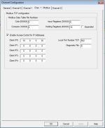
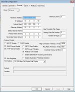
Also performed the setup in the channel configuration (see attached pictures). Not sure if this is correct?

I want to test my messaging before I send the PLC in the field so I'm convinced it actually is sending the registers that I desire. Someone told me I could use a program called Modbus Poll to check to see if the registers are coming across (Modbus Poll gives you a 30 day trial). I tried downloading this and "connecting" and didn't have any luck connecting...not sure why. Has anyone used this or similar program to check Modbus connection?

THANKS in advance! First timer working with Modbus messaging! I hope someone can help me here so I don't dread having to do it in the future :)
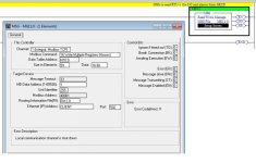
msg Modbus.jpg chan 1 - modbus.jpg channel 1.jpg
 
if your plc is the slave, you dont need to use message blocks. enable modbus tcp on the ethernet port and then put in the datafile number for each of the respective modbus function codes in the comm channel setup.

since he wants his points formatted in a certain order, you may need to use move blocks to order the data into new data files in the order that he wants.

Thanks for the tips.
I did do the modbus tcp enable.
I did put in the respective datafile number.
"since he wants his points formatted in a certain order, you may need to use move blocks to order the data into new data files in the order that he wants." I guess I'll have to figure this out. It appears that he's doing it "in order" based on his spreadsheet.

Has anyone used any "testing" programs to ensure the modbus information is actually being sent from the PLC?
 
As mentioned before, as a 'slave' unit you don't have to do any logic to reply to queries from the 'master' unit.

Just fill in the information in the N10 files. Use the other unit to indicate if it got the information. Use whatever tools exist to read the 'master' units data tables which are the targets of its Modbus reads.
 
also, you have to power cycle the plc to get it to take the modbus tcp enable. if you havent done that, that may be why you arent seeing anything with modbus poll.
 
also, you have to power cycle the plc to get it to take the modbus tcp enable. if you havent done that, that may be why you arent seeing anything with modbus poll.

Thanks for this tid-bit. I'll try power cycling the PLC when I'm back in front of it.

And Bernie thanks for confirming. I attached pictures of how I set this up in my original post, I think what I did is correct.
 
are you planning on handing off floating point data to the master plc? if so you will need to use a cop instruction to convert the F datatype to N datatype, which will then be read as 2 16 bit registers combined into a 32 bit float on the master side.
 
are you planning on handing off floating point data to the master plc? if so you will need to use a cop instruction to convert the F datatype to N datatype, which will then be read as 2 16 bit registers combined into a 32 bit float on the master side.

I have 3 analog outputs that are F datatypes.
Does anyone have an example of how to use a COP instruction for doing this?

----------------------------
Also the guy programming the master PLC wants me to create a "watchdog timer" so he can make sure he's getting communications with my PLC. Any examples for doing this?

Another concern I have: all the registers I'm sending the guy to his GE PLC do not have tags (symbols); only descriptions. Do I NEED to have tags (symbols) for the data I'm sending over Modbus, or will descriptions suffice?

I know I'm throwing a few questions out there, this is stuff I haven't encountered before and hopefully you guys can open my eyes...:site:
 
Last edited:

Similar Topics

I'm still a beginner when it comes to PLC's programming in general but I've had a fair bit of experience with SLC 500's and micrologix, but I've...
Replies
3
Views
1,511
Hi Guys, I have a project that requires a M340 PLC to communicate with a PM5340 power meter over Modbus TCP. I have previously used the same type...
Replies
3
Views
3,272
Hi all, I’m developing a critical application in a TSXP574634M Premium Telemecanique processor (With Unity Pro and native Ethernet port). The...
Replies
1
Views
4,700
Apologies for not being the best IDEC programmer. I recently was doing some inspections on a site that had 3 FC6A IDEC processors. The issue is...
Replies
0
Views
41
Good morning fellow sea captains and wizards, I am being asked to do the above and obtain 4 values from each slave, I know about the MRX and MWX...
Replies
20
Views
221
Back
Top Bottom