RTD to PLC

ChaBoki

Member
Join Date
Dec 2015
Location
Malaysia
Posts
18
hi guys,

im kind of new to PLC programming, there's a project i need to complete and it's related to heating.

i did the PLC program in TIA V13 and the wiring for the TT.
The problem i'm facing is that the TT isn't sending any signal to my Analog input ( AI 8 x 13 bit )
The TT with transmitter is calibrated with no problems.
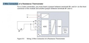
The wiring are based on manuals I've download from the internet. (two wire)

i've attach a picture of scale which is one of the block to read the signal of RTD and IW298 is suppose to be from the TT.
" http://imgur.com/j60XFkk "

as you can see the signal from IW298 is "0".

Just wondering who can help me because I've been dealing with this problem for 2 days with no progress at all.
any help would be great. :D
and again, i new to this and did not have any proper PLC lesson. if would be great if you experts can help.
i will send my full program for the scale,con_c and unscale if requested.
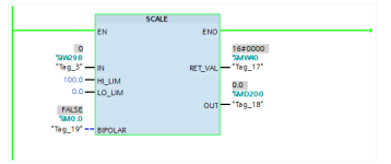
scale.PNG
 
Are you powering the current loop with 24VDC??? or is the PLC analog input configured for active?
What is the ref. of the analog input card etc.
 
Are you powering the current loop with 24VDC??? or is the PLC analog input configured for active?
What is the ref. of the analog input card etc.
Yes I am powering the current loop with 24VDC.
and I am not quite understand what you mean by PLC AI configured for active.

ref. for AI 8x 13 Bit ( 331-1KF02-0AB0 )
 
The problem could be in the way you've wired the transmitter to the analog input channel or in the way you've configured the channel.

First try to measure the signal with your multimeter. If there is no signal, the value of zero in %IW298 could be correct.

Are you sure that the address %IW298 is associated with the analog channel you've wired the transmitter to? Are you sure the analog channel is configured for 4 -20 mA And not voltage?
 
"I am not quite understand what you mean by PLC AI configured for active."

You should read the manual of the analog card.

In what position is the switch on the side of the analog card (ABCE) for the input?
If passive, it must be "C"
 
Last edited:
The problem could be in the way you've wired the transmitter to the analog input channel or in the way you've configured the channel.

First try to measure the signal with your multimeter. If there is no signal, the value of zero in %IW298 could be correct.

Are you sure that the address %IW298 is associated with the analog channel you've wired the transmitter to? Are you sure the analog channel is configured for 4 -20 mA And not voltage?

i am so sure that the TT can gives 4 - 20mA. But when i connect it in Analog Input Module, the program show 0 value for %IW298.
Even when i replace TT to multi function calibrator and inject 4 - 20mA into AI module. it's still value 0 in the program.

%IW298 is associated with the right analog channel.
The analog channel is already configured for 4 - 20mA.

now, i suspect the analog input has broken. but don't really know whether its really broken or not.

Edit - Even when i changed to another analog input module like 8 x 13 Bit, the value is still 0.
so its not the analog input module's fault? i am so confused really.
 
Last edited:
"I am not quite understand what you mean by PLC AI configured for active."

You should read the manual of the analog card.

In what position is the switch on the side of the analog card (ABCE) for the input?
If passive, it must be "C"
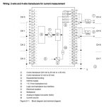
i followed the steps from the module's manual and uses D from the (ABCD) for two wire connection.
if i'm wrong please correct me.
 
Last edited:
I cant say for sure, just make sure your wiring is correct.

I have only used TIA with 1200 series components, so I'm not much use for the older hardware.

Capture.jpg
 
I cant say for sure, just make sure your wiring is correct.

I have only used TIA with 1200 series components, so I'm not much use for the older hardware.
i am currently using AI 8x 13 Bit ( 331-1KF02-0AB0 )
so my wiring should look like this.

Screenshot_2015-12-02-02-19-57.jpg
 
Last edited:
You have a 4-20mA sensor and you wired it up like it is a RTD sensor.


edit: you changed your schematics. This is better. So, do you have a passive or active transmitter? And how did you connect it, 2-wire or 4 wire?
 
Last edited:

Similar Topics

How do you program a Micrologic 1200 RTD module using a Micrologic 1400 PLC? I'm using RSLogix Micro to program the ladder logic. I've wired the...
Replies
4
Views
2,833
I'm an aspiring instrumentation engineer. I need to connect following to the PLC Micrologix 1100 RTD "PT100" the input module is AI 0-10v can I...
Replies
6
Views
3,479
Hi, We have RTDs connected to a Siemens PLC S7-315 system. Out of the 15 or so RTDs connected, all show correctly except for 5. For all these 5...
Replies
2
Views
1,894
I am trying to use the Siemens S7-300 PLC system to monitor temperature changes using a two wire 100ohm platnium RTD. I am using a SM331 AI...
Replies
2
Views
13,635
Good Morning , I have a RTD , that I would like to wire into a 1756-IF8 Analog Input Card. Would you all a simple wiring diagram , of what...
Replies
4
Views
1,181
Back
Top Bottom