AI Input Channel Not Detecting

goodoboy

Member
Join Date
Aug 2010
Location
Houston
Posts
86
Hello all,

I have 2 devices in the field that outputs 4-20mA (scaled 0-100%) on the PLC.

The value in the program reads 104% on both channels regardless what the 4-20mA is sending. Even if I disconnect the cable going into the channel.

Has anyone had this problem before? I am trying to troubleshoot. Maybe the inputs don't except 4-20mA, only volts.

I attached some screenshots.

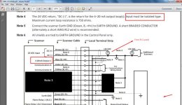
One thing I am puzzled on is the output device states isolated inputs only, but the AI card is non-isolated.

Thank you kindly.

Screenshot_7.jpg Screenshot_8.jpg Screenshot_11.jpg Screenshot_9.jpg Screenshot_10.jpg
 
Is the channel that you are bringing the 4-20 mA signal in to configured for 4-20 mA input? Also, on screen shot 11, I don't see your 750 ohm resistor. In cases like this, I set up a DC power supply with a decade box and rheostat to generate a current. I then connect it to the analog input channel and look for a reading. If you can verify that the PLC system is processing the current signal, then you must look outward to see why you are not getting a signal on your analog input channel.
 
Several things can be happening.

1) There could be a misconfiguration issue.

2) The maximum 750 ohms referred to is a maximum loop value. Your 4-20mA analog input probably wants a 100 ohm or a 250 ohm resistor across the input to create an IR voltage drop. You need to check the wiring specs for the AI card and see if the 4-20mA dropping resistor is 'built-in' or whether it is a separate resistor that you wire across the terminals.

3) Off-scale, up-scale is a common failure mode indication, which can happen from a multitude of different issues, like no current/voltage 'seen' at the input.

4) The scanner device is effectively a single ended 3 wire, active 4-20mA output that shares a common/ground with the 24Vdc power supply.

If both of your scanners are using different power supplies powered from different AC circuits, you could have excessive common mode voltage driving the signal off scale up scale.

The scanner's requirement for 'isolated analog inputs' is to avoid the noise and common mode issues associated with grounding, particularly between different scanners.

Troubleshooting:

1) You need to simulate 4-20mA from a signal source/calibrator or power supply and resistance network to see what you need to do to get your AI read any 4-20mA signal.

Disconnect both scanners and preferably use a battery powered 'source' so that common mode is not an issue.

Your card is well marked as non-isolated so it probably doesn't tolerate too much common mode. Even a series resistor network can common mode, depending on where you connect in the series.

2) Once you get the AI reading some reasonable 4-20mA value, connect one scanner to that AI and see what you get.

If it works OK but then goes off-scale upscale when you connect the 2nd scanner signal, then you'll need to get a 4-20mA loop isolator module to isolate the 2nd signal.
 
Is the channel that you are bringing the 4-20 mA signal in to configured for 4-20 mA input? Also, on screen shot 11, I don't see your 750 ohm resistor. In cases like this, I set up a DC power supply with a decade box and rheostat to generate a current. I then connect it to the analog input channel and look for a reading. If you can verify that the PLC system is processing the current signal, then you must look outward to see why you are not getting a signal on your analog input channel.

Thank you for replying.

The channel is configured for 0-20mA as shown on the pictures.

I have other 4-20mA signals that is configured for 10V signal that is tied to the AI card, like a regular transmitter.

The device spec (picture 11 ) states 750ohm max loop resistance. Does this mean I need to connect a 750 ohm resistor on the channel input? The other AI channels have a 250ohm resisters on the inputs and works fine.

Thank you
 
one thing I noticed that could make the difference is in screenshot 11 it clearly stated that the "Inputs must be isolated type" but the AI card is not isolated that would make big difference
just something to check
 
Several things can be happening.

1) There could be a misconfiguration issue. We checked the scaling configuration and only 0-20mA is available. Tomorrow I take a screen shot of the scaling configuration from the 4-20mA devices that is working on the same AI card. They are configured for volts inputs, and have 250 ohms across the inputs.

2) The maximum 750 ohms referred to is a maximum loop value. Your 4-20mA analog input probably wants a 100 ohm or a 250 ohm resistor across the input to create an IR voltage drop. You need to check the wiring specs for the AI card and see if the 4-20mA dropping resistor is 'built-in' or whether it is a separate resistor that you wire across the terminals. I will check for this.

3) Off-scale, up-scale is a common failure mode indication, which can happen from a multitude of different issues, like no current/voltage 'seen' at the input.

4) The scanner device is effectively a single ended 3 wire, active 4-20mA output that shares a common/ground with the 24Vdc power supply. This is correct

If both of your scanners are using different power supplies powered from different AC circuits, you could have excessive common mode voltage driving the signal off scale up scale.

The scanner's requirement for 'isolated analog inputs' is to avoid the noise and common mode issues associated with grounding, particularly between different scanners. Both scanners use the same 24Vdc power supply

Troubleshooting:

1) You need to simulate 4-20mA from a signal source/calibrator or power supply and resistance network to see what you need to do to get your AI read any 4-20mA signal. We will try this tomorrow. We can drive the 4-20mA with 744 communicator

Disconnect both scanners and preferably use a battery powered 'source' so that common mode is not an issue.

Your card is well marked as non-isolated so it probably doesn't tolerate too much common mode. Even a series resistor network can common mode, depending on where you connect in the series.

2) Once you get the AI reading some reasonable 4-20mA value, connect one scanner to that AI and see what you get.

If it works OK but then goes off-scale upscale when you connect the 2nd scanner signal, then you'll need to get a 4-20mA loop isolator module to isolate the 2nd signal.


Thank you
 

Similar Topics

We have a Rockwell 1734 IE8C 8 channel analog input card, but we don't know if this is sourcing or sinking. The user manual doesn't seem to have...
Replies
6
Views
1,112
Dear All I am currently trying to configure my S7-1500 CPU to read a 4-20mA value at channel 1 Analog Input Card Module (6ES7531-7KF00-0AB0) 4...
Replies
14
Views
2,819
I have two cards (IB8S/B) on which safety input channel goes to fault about once per day (point status goes to 0). Inputs are related to two...
Replies
2
Views
1,319
Good evening, just a dump question, I’ve configured channel no 13 with scalling as attached, then shown not linear reading, even when i simulate...
Replies
6
Views
1,700
Hi all, We tried to setup the hardware onto a 10 slot rack as follows, PS Slot 0: 5580 controller Slot 1: Safety Partner Slot 2: Safe Inp Slot...
Replies
8
Views
2,713
Back
Top Bottom