SLC Timer Glitch

CanSpellPLC

Member
Join Date
Sep 2020
Location
USA
Posts
12
I want to start off by saying that this is not really good programming practice, but after looking through some PLC's that were causing equipment malfunctions, I found an interesting glitch that can occur. We had a few pieces of equipment that were occasionally unable to be started or stopped from the board operator or started from the field operator. After looking through the programming I came across a rung that would occasionally cause the timer to hold true and not release.

I looked across forums and within the documentation to see if anyone has come across this issue or if Rockwell says that you shouldn't set up a rung this way, and I was unable to find anything. I'm just putting this out there for discussion and to hopefully help someone if they have the same issue.

This was on a few of our SLC's, the equipment that was susceptible to this glitch had rungs that were set up as follows:

(apparently spaces are removed when this is posted, so I used periods instead of spaces)

HMI Pushbutton............................ Timer.DN..............................Timer

[ ] ------------------------------------- [ / ] --------------------------(TON)
.......................................|
.......................................|
.......................................|
.......................................|
Timer.TT ..........................|
[ ] --------------------------


If you can't tell from the crude text drawing, a pushbutton from the HMI initiates a timer (in this case, to ensure a mechanical motor contactor pulls in or drops out), the timer becomes true and the .TT seals in the rung around the momentary pushbutton. Once the timer completes, the .TT bit should open, and presumably the XIO .DN should also open and the timer should drop out.

What I've noticed ends up happening occasionally is, depending on when the timer completes in relation to where the PLC is in it's clock cycle, the timer .DN can become true (making the rung false and resetting the accumulated time) but the .TT instruction true which passes through XIO .DN instruction on the rung and maintains the .EN on the timer. When this occurs, the timer instruction stays true, time does not accumulate, and the .TT stays true because the accumulated time never increases to meet or exceed the preset. To fix this, I just removed the .DN XIO instruction as this was unnecessary since the .TT would produce the same intended result.

Again, this does not happen every time, but the location of the rung within the file certainly dictates the probability of this occuring.


Has anyone else experienced this or is this a known issue?
 
Last edited:
I think you will find the issue is more to do with the HMI momentary contact, and not the timer.
Some HMI's that have a momentary button, are supposed to set a bit "high" for a defined period, then set the bit "low" again. This doesn't always happen. Sometimes the bit does not reset.
I find it better to set the bit with the HMI, then reset the bit in the PLC logic.
Agree with that. HMI should do one thing and one thing only. Set it and forget it.
 
[OP: put {code}...{/code} - replacing { with [ and } with ] - around stuff where you want to do ASCII graphics. {ladder}...{/ladder} is alternate, but I never saw the advantage to that.]


I understand that the [XIC Timer.TT] seal-in branch should be redundant with the [XIO Timer.DN].


I have also heard of the the "stuck HMI Pushbutton bit" issue*.


But if the latter were the cause, why would the OP's removal of the [XIO Timer.DN] fix the problem? And does it really fix the problem or just make it more rare? Finally, wouldn't OP have noticed that the [HMI Pushbutton] does not become 0?


I have a MicroLogix 1100; is that similar enough to the SLC? I could run some tests.


Sidebar: Does removing the [XIC Timer.TT] also fix the problem?


* My brother told me about this; his theory is that in the E/IP scheme that sends multiple duplicate packets to increase reliability, an [assign a 1] request arrives after the last [assign a 0] request, because TCP/IP and Ethernet are not deterministic.
 
Last edited:
But if the latter were the cause, why would the OP's removal of the [XIO Timer.DN] fix the problem? And does it really fix the problem or just make it more rare? Finally, wouldn't OP have noticed that the [HMI Pushbutton] does not become 0?

Possibly the OP is only using the .TT timer bit. If the .DN was removed and the HMI button got stuck the .TT would go off when the timer completes but the timer would not reset.
 
Possibly the OP is only using the .TT timer bit. If the .DN was removed and the HMI button got stuck the .TT would go off when the timer completes but the timer would not reset.


Hmm, but that still does not explain why they do not see that the HMI button is stuck; OP* is unlikely to miss that.


* who understands that the [XIC Timer.TT] seal-in is redundant with the [XIO Timer.DN] (IFF [XIC HMI Pushbutton] result is false i.e. (HMI PB] is 0).
 
I've been looking all over to see if there is something else writing to any of these bits, but I can't find anything (assuming there is nothing undocumented coming from an external device). This has been an issue on a few PLC's, with the same logic. I can't replicate it on a PLC sitting on my desktop, but I don't know if that would be an ideal test anyways as most of these field devices are loaded up pretty good and are under quite a bit more processing load.

I have checked the HMI and none of them are set up incorrectly (with the way they are implemented). It's still not ideal, as they are direct inputs from the HMI rather than toggle and reset from the PLC.

All of my testing so far tracks back to this seeming like a glitch as the following occurs when the "glitch" comes in:

1. The timer's ACC gets reset
2. The .TT stays true
3. The .DN stays false (it's an XIO so the timer stays enabled)
 
The only other thing that I can't rule out, is that the HMI bit is being seen on the RSLogix 500 program as false, but is actually being written high/low at too fast of a rate to be seen in the program. Although, this still would not explain why the timer would reset but not begin to accumulate when it gets relatched by the .TT bit.

If the timer just kept resetting and starting over, that would definitely point me in the direction of the HMI bit oscillating, but with it simply resetting and then holding steady at 0, it keeps bringing me back to my original thought of a timer glitch.

Anyone have any other thoughts?
 
Last edited:
Anyone have any other thoughts?


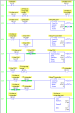
MicroLogix 1100 test program in image below and in attached .ZIP.


If SLC timer is different has the glitch suggested by OP i.e. /TT=1 somehow survives timer reset, then this program will identify it by the counters incrementing. On SLC it would need to use a different bit in S:4 on Rung 0000; as the SLC free-running clock is 100Hz, I think S:4/4 is 160ms on, 160ms off, and should work similarly with the 250ms timer.


Analog for OP's rung is Rung 0004 here. All counters are 0, so no evidence of hung /TT bits yet.


xxx.png

  • S:4/11, from 10kHz free-running clock, is 204.8ms on, 204.8ms off
    • Is a proxy for the HMI Pushbutton in OP's rung
  • B3:0/0 is copy of S4:11 i.e. 204.8ms on, 204.8ms off
  • B3:0/2 is one-shot of rising edge of 204.8ms on
  • B3:0/0 is trigger: becoming 1 starts timer
    • Timer /TT becomes 1, seals-in lower branch of rung 0004
    • Timer /EN becomes 1
      • B3:0/4 is one-shot of rising edge of timer /TT
  • Timer preset is 250ms
  • At 250ms + epsilon
    • 250ms > 204.8ms, so at that point B3:0/0 trigger is off
      • And will stay off for another ~ 159.6ms
      • This duplicates the same behavior as OP's momentary HMI Pushbutton
    • Timer /TT becomes 0
    • Timer /DN becomes 1
    • Timer is reset after rung 0004
      • Timer /EN, /TT, /DN all become 0
  • Counter on Rung 0002 never incrementing assures that B3:0/0 trigger is never on when timer completes (/DN becomes 1)
  • Counter on Rung 0003 never incrementing assures that timer is never timing and is never enabled when trigger rising edge occurs
  • Counter on Rung 0006 never incrementing assures that trigger rising edge and /TT rising edge only ever occur on the same single scan
  • Counter on Rung 0007 is number of 204.8ms on rising edges, and is over 7500 as I post this.
The S:4 bit and the timer .PREset are related, so this could run much faster; I wanted to be able to watch it somewhat.
 
Tweaked the test program some

  • Add more consistency checking (counters not incrementing assures that ...)
  • Add 51ms in-program-scan delay on scans where the trigger starts the timer.
    • To investigate if the millisecond Timer.ACCumulator (Timebase = 0.001s) advances during the scan: it does not
      • So apparently the timer actually timing - advancing .ACCumulator and assigning /TT and /DN bits based on .ACC and .PREset comparison - occurs only during inter-program-scan periods, similar to I/O scans in synchronous PLCs (e.g. A-B non-Compact/ControlLogix)
      • The timer instruction itself seems to only be used for assigning 1s or 0s to .EN and .TT, i.e. start/continue timing or reset.
Although my tests are on MicroLogix and not on SLC H/W, OP needs to investigate the alternate cause proposed by @chelton and @lee1968nh: the {HMI Pushbutton] bit that the PLC sees is not momentary in practice i.e. it is not being returned to a value of 0 before the timer is done, and a better solution is to have the PLC unlatch {HMI Pushbutton} after the timer starts, e.g.


Code:
      HMI PB
---+---] [------+---+---[Timer ]---+---
   |            |   |              |
   |  Timer/TT  |   |    HMI PB    |
   +----] [-----+   +-----(U)------+
 
Yeah this is interesting, you're definitely making me second guess my initial thought. I can't replicate this on my bench at all, but there doesn't appear to be anything in the programming that looks to be writing over anything.

Am I wrong in thinking that this is a simple enough rung now that the HMI pushbutton should be out of the question as a suspect? If, hypothetically, the HMI is staying locked in or oscillating, the .TT should latch in the timer and it should I should still see it accumulate. I'm at a loss at the moment.

Thank you so much for the input so far, this has made me dive deeper than ever into how the PLC steps through everything. I'll be sure to report back if I can replicate it or figure anything out.
 
Am I wrong in thinking that this is a simple enough rung now that the HMI pushbutton should be out of the question as a suspect? If, hypothetically, the HMI is staying locked in or oscillating, the .TT should latch in the timer and it should I should still see it accumulate. I'm at a loss at the moment.


Yes, the timer will be a repeating timer if the HMI Pushbutton stays 1 and has both the [XIC .TT] seal-in branch and the [XIO .DN].


Without the [XIO .DN] it will run to completion once and then hold.


For the former case, the .DN will be mostly 0 with a one-shot/one-scan 1 every .PREset time units, and the .TT being the opposite (mostly 1 with a one-shot 0)


For the latter case .TT and .DN will be off and on, respectively.
 

Similar Topics

Good day all. I have attached two ladder diagrams. What I'm attempting to do with the one named "lift timers" is to lift a basket out of an acid...
Replies
11
Views
3,736
I have a program running in an SLC 5/01. I have two rungs in the same ladder that can enable a timer. When either rung goes true, the timer EN...
Replies
12
Views
3,329
Trying to control some outputs using AB SLC 150 1745-LP151, 1745-E103, and 1745-E105 Trying to control outputs using an RTF timer as I want the...
Replies
22
Views
6,173
____internal______backup _____________________one scan ____pulser________function_____________________pulse at ____50ms...
Replies
2
Views
3,474
Anybody out there know exactly where a timer's time base data is stored in memory for a SLC 500? Is it in the reserved portion of the timer...
Replies
5
Views
5,077
Back
Top Bottom