You are using an out of date browser. It may not display this or other websites correctly.
You should upgrade or use an alternative browser.
You should upgrade or use an alternative browser.
GX developer: I don't understand this pump starting logic...
- Thread starter Mas01
- Start date
glenncovington
Lifetime Supporting Member
Looks like a latched output. Pump starts at 80cm level and is unlatched when less than 24cm.
glenncovington is correct. It is a latching circuit. When the level is above 80 cm, it will obviously be over 24 cm, energizing the output. Since the output is energized, the contact in parallel with >80 cm is also energized, giving a path around. Once the level drops below 24 cm, the rung will be false, the pump will de-energize, and the pump will not energize again until the level rises above 80 cm once again.
Basically, once the level is above 80 cm AND above 24 cm, turn on the pump. Also, while the pump is energized AND the level is above 24 cm, keep the pump on.
Basically, once the level is above 80 cm AND above 24 cm, turn on the pump. Also, while the pump is energized AND the level is above 24 cm, keep the pump on.
drbitboy
Lifetime Supporting Member
@glencovington and @MikeyN got there first, but I will try to state it in a different way.
I supect you are reading that logic as
By De Morgan's theorem, "Run if ... AND NOT ..." can be rewritten as
But please Do Read!
That is a canonical Start/Stop pattern. Cf. here:
https://www.contactandcoil.com/patterns-of-ladder-logic-programming/startstop-circuit/
I am amazed that anyone does not recognize and understand it as such; it is the canonical first or second example for teaching the reading and understanding of ladder logic; your teachers, not you, should be embarrassed; if you are self-taught, then it is understandable, but it needs to be rectified ASAP! Seriously mate, the Start/Stop pattern occurs over and over and over and over and over in many different forms; any of its Start, Stop, Seal-in or Run sub-systems may be composites of multiple conditions and not just solitary NC/NO/Outputs, but the overall logic is always the same.
The [D353 > 240] is the Stop condition, or, perhaps more accurately, expresses the Stop condition, and could perhaps be more clearly understood as [NOT (D353 <= 240)] i.e. "allow the pump to run if and only if the level is not at or below the low level," which is the same as "do not run the when the level is at or below the low level."
The [D353 > 800] is the Start condition. The pump starts when the level is above 80cm. The second condition, [D353 > 240] must also be true of course, but since 800 > 240 if the former is true then the latter will be true.
The [NO Y2D5] is the Seal-in condition. It cannot cause the pump to start on its own, but once the Start condition (above) does that, the Seal-in will keep the pump running even after the Start condition is no longer true. It expresses "Pump is running" or "Pump was running at the end of the last scan" or "Pump was previously started and has not yet stopped."
So the entire rung could be read as
https://www.youtube.com/watch?v=T3tnXu-Eywc&list=PLB1ACAF773A15BFB1
I supect you are reading that logic as
Start pump if ... AND (level is above 24cm)
but another way of reading that is
Run pump if ... AND (level is NOT at or below 24cm)
Note the use of Run instead of Start: every scan of the ladder logic is a fresh start at looking at input and internal values and responding by assigning values to internal and output values.
By De Morgan's theorem, "Run if ... AND NOT ..." can be rewritten as
Do NOT run pump if ... OR (level is at or below 24cm)
TL;DR
But please Do Read!
That is a canonical Start/Stop pattern. Cf. here:
https://www.contactandcoil.com/patterns-of-ladder-logic-programming/startstop-circuit/
I am amazed that anyone does not recognize and understand it as such; it is the canonical first or second example for teaching the reading and understanding of ladder logic; your teachers, not you, should be embarrassed; if you are self-taught, then it is understandable, but it needs to be rectified ASAP! Seriously mate, the Start/Stop pattern occurs over and over and over and over and over in many different forms; any of its Start, Stop, Seal-in or Run sub-systems may be composites of multiple conditions and not just solitary NC/NO/Outputs, but the overall logic is always the same.
The [D353 > 240] is the Stop condition, or, perhaps more accurately, expresses the Stop condition, and could perhaps be more clearly understood as [NOT (D353 <= 240)] i.e. "allow the pump to run if and only if the level is not at or below the low level," which is the same as "do not run the when the level is at or below the low level."
The [D353 > 800] is the Start condition. The pump starts when the level is above 80cm. The second condition, [D353 > 240] must also be true of course, but since 800 > 240 if the former is true then the latter will be true.
The [NO Y2D5] is the Seal-in condition. It cannot cause the pump to start on its own, but once the Start condition (above) does that, the Seal-in will keep the pump running even after the Start condition is no longer true. It expresses "Pump is running" or "Pump was running at the end of the last scan" or "Pump was previously started and has not yet stopped."
So the entire rung could be read as
Run the pump if (EITHER the level is above 80cm OR the pump is already running) AND (the level is not at or below 24cm).
I strongly suggest watching Ron Beaufort's Level 0 intro series to ladder logic; it takes less than 2h but will set one on the right track forever more:
https://www.youtube.com/watch?v=T3tnXu-Eywc&list=PLB1ACAF773A15BFB1
Last edited:
Mas01
Member
Really appreciate the answers! It makes sense now that it's been explained (and yes, I did read all of your post @drbitboy, many thanks).
For the record I am completely self-taught and have had no formal training whatsoever. Hence, all the questions I keep posting on this forum.
Cheers
For the record I am completely self-taught and have had no formal training whatsoever. Hence, all the questions I keep posting on this forum.
Cheers
Last edited:
Hence, all the questions I keep posting on this forum.
Cheers
I know of no better place to ask. This forum is a treasure.
This is a common way to do a latch (RS) as many people seem to think that the SET/RESET is bad, there are a few things to consider that in some PLC's using a SET/RESET may stay latched if powered down even though the SET enable is not true this is just some people who believe that a SET/RESET cause problems that is not true, it's the original programmer has used them in a way that makes it difficult.
The US seem to call them SEAL in circuit but it is essentially a SET/RESET so you set the bit by making it true & ORING that bit round the bit that makes it true so in effect you latch it.
The reset is effectively a NOT that drops it out. this is the same as in logic using relays, you can get SET/RESET relays that use magnets to hold the relay in then there are two coils that either SET or RESET the relay, if powered down then they maintain their state, the other is obviously the standard relay where you energise the relay & then use a spare contact to "LATCH" it in.
The are some caveats, some S/R relays in PLC's are edge triggered some are SET before Reset or RESET before SET.
The equivelent of the logic you have is
> Dxx K820 SET Yxx
< DXX K250 RST Yxx.
As in Mitsubishi outputs are non retentive and only updated at end of scan (unless forced to do immediate update) then providing Dxx is less than K820 it will not latch even if it is above K250.
Mas01
Member
This is a common way to do a latch (RS) as many people seem to think that the SET/RESET is bad, there are a few things to consider that in some PLC's using a SET/RESET may stay latched if powered down even though the SET enable is not true this is just some people who believe that a SET/RESET cause problems that is not true, it's the original programmer has used them in a way that makes it difficult.
The US seem to call them SEAL in circuit but it is essentially a SET/RESET so you set the bit by making it true & ORING that bit round the bit that makes it true so in effect you latch it.
The reset is effectively a NOT that drops it out. this is the same as in logic using relays, you can get SET/RESET relays that use magnets to hold the relay in then there are two coils that either SET or RESET the relay, if powered down then they maintain their state, the other is obviously the standard relay where you energise the relay & then use a spare contact to "LATCH" it in.
The are some caveats, some S/R relays in PLC's are edge triggered some are SET before Reset or RESET before SET.
The equivelent of the logic you have is
> Dxx K820 SET Yxx
< DXX K250 RST Yxx.
As in Mitsubishi outputs are non retentive and only updated at end of scan (unless forced to do immediate update) then providing Dxx is less than K820 it will not latch even if it is above K250.
Many thanks for this. The previous author(s) have mostly used SET/RST commands for pump control, so when I saw the latching code for the first time, it threw me. Cheers.
Mas01
Member
Hi again.
I'm returning to this thread because the operator has asked me to implement a change.
I understand the code in the original post and the pump is behaving exactly as expected, ie the pump turns ON at 800mm water level , and stays on until the level drops to 240mm. Now the operator wants to have a manual override, so that they can switch the pump on/off at will, but only when the level is between 240 and 800mm. IE below 240mm or above 800mm , the operator is locked out & cannot manually operate the pump.
To start the pump manually involves two inputs: a click on a screen to select the pump (a bit value let's call it M1) followed by a physical START pushbutton (a digital input let's call it X1). Both of these need to be TRUE/1.
To stop the pump, M1 must be true and The STOP button must be pressed (let's call it X2).
I was thinking along the lines of this (M3 is a bit representing a request to start/stop the pump)
---|M1|---|X1|---[SET M3]-------|
---|M1|---|X2|---[RST M3]-------|
Then do a check to make sure water level is within range 240 to 800mm (let's call that M4).
Then somehow feed M3 (the manual start/stop request) and M4 into the pump control logic as shown in post #1. But I'm not sure what that should look like.
Sorry for the poor formatting, all this is written from my phone. Thanks in advance.
Last edited:
drbitboy
Lifetime Supporting Member
See below.
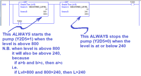
In that middle case, the upper branch [Is Level>800?] will evaluate to False, but low level test [Is Level>240?] will evaluate to True, so the output state of Y2D5 after the entire rung is evaluated is dependent on the input state of Y2D5 before the entire rung is evaluated.
So while we may normally read that Start/Stop Circuit pattern as
- The [Is Level>800?] will always start the pump when it evaluates to True, and
- the [Is Level>240?] will always stop the pump when it evaluates to False,
- so maintaining that "line" of logic will always override whatever you do with the operator-override logic.
In that middle case, the upper branch [Is Level>800?] will evaluate to False, but low level test [Is Level>240?] will evaluate to True, so the output state of Y2D5 after the entire rung is evaluated is dependent on the input state of Y2D5 before the entire rung is evaluated.
So while we may normally read that Start/Stop Circuit pattern as
- Assign 1 to the value of Y2D5 IF
- BOTH (Level>800 OR Y2D5=1)
- AND (Level>240)
- Assign 1 to the value of Y2D5 IF
- EITHER
- BOTH [Level>800] AND [Level>240]
- OR
- BOTH [Y2D5=1] AND [Level>240])
- EITHER
- ... to which we can add another OR condition, i.e. the operator override:
- OR
- BOTH [THIS_PUMP_SELECTED=1] AND [START_THIS_PUMP=1] AND [Level>240]
- OR
- ... with the confidence that,
- If the level is below 240,
- then the new operator start override branch will do nothing,
- because the AND [Level>240] will be False
- then the new operator start override branch will do nothing,
- If the level is above 800,
- then the new operator start override branch will do nothing net (i.e. other than what would have already been done),
- because it will be ORed with an already True branch ([Level>800] ...)
- then the new operator start override branch will do nothing net (i.e. other than what would have already been done),
- If the pump is already running (Y2D5=1),
- then the new operator start override branch will do nothing net,
- because it will be ORed with an already True branch ([Y2D5=1] ...)
- then the new operator start override branch will do nothing net,
- If the level is below 240,
- ... so with those three cases covered, the operator start override cannot have any net effect when
- EITHER the level is outside the limits,
- OR the pump is already running,
- which was one of the design conditions.
- So now we want to consider what happens when the level is between the limits and the pump is not already running, and the operator start override becomes 1:
- which is simple: since it is ORed with the [Level>800] branch, it will have the same effect as if [Level>800] evaluates True; i.e. the pump will come on for this scan, and on subsequent scans the seal-in [Y2D5=1?] will maintain the pump on, until [Level>240?] becomes False.
Last edited:
drbitboy
Lifetime Supporting Member
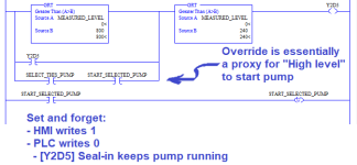
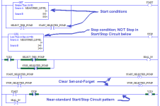
Based on the previous post, the branch added under the [Is Y2D5=1?] seal-in branch adds the operator's manual override to start the pump when the level is between 240 and 800 in the image below:Note that the start event is effectively one-shot, set to 1 from the HMI and immediately cleared to 0 by the PLC after it is tested:
It is worthwhile re-reading this Start/Stop Circuit pattern page, and paying particular attention to the "trigger dominant" vs. "stop dominant" aspects of the discussion.
-
- if the start event causes the pump to start on one scan; the seal-in will keep the pump running on subsequent scans until the it is stopped because of either a low level or the stop event (details TBD);
- if the start event occurs while the level is above 800, it does not matter because the high level will already have caused the pump to start on this or a previous scan;
- if the start event occurs while the level is below 240, the pump will not start because of the low level;
- because the bit is cleared to 0, it will not be hanging around like a stale f@rt to effect any changes on subsequent scans.
It is worthwhile re-reading this Start/Stop Circuit pattern page, and paying particular attention to the "trigger dominant" vs. "stop dominant" aspects of the discussion.
-
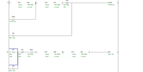
As you are not that experienced, I have created a simple manual control ignore the bit & I/O numbers just used any you will need to allocate your own, basically the original control stays but to make it simple I have just created a separate rung for manual interlocking it, before DR starts to rip it apart & make it one rung I did this as it would be easier for you to comment & understand & test the manual without actually putting it fully in place.
The idea is to have an HMI button called Auto/Man if off it will be in auto, so the system runs as is, make this button a toggle i.e. one press it turns it on & another press it turns it off, also change it's colour & text based on if it's on or off.
The bottom logic (although duplicating some of the auto logic) is basically the same but gives the operator manual control.
Note: my M3 is the manual on/off latch.

drbitboy
Lifetime Supporting Member
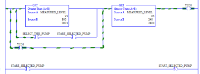
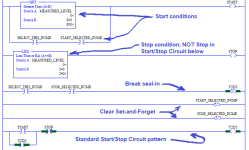
The final step is where we add the operator's manual stop override, which is only to be effective when the measured level is between the low (240) and high (800) level limits. Furthermore, we can also assume the stop override is only effective when the motor is running: if the motor is already stopped, then we do not care if the operator wants it to stop.
For those conditions, the logic will look like this imagewhere the green-highlighted paths indicate True conditions; every other path is False*. Note that the output rung of the [Is Level>800?] instruction is False, as are those of the [select this pump] and [start selected pump] instructions, while both input and output rungs of the [Is Level>240] instruction are True; all of that together tells us that the level is beween the trigger limits, and the seal-in [Is Y2D5=1?] instruction branch is what is keeping the pump running.
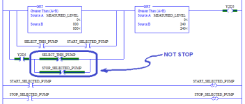
Looking at that, it should be obvious that the place where the operator's manual stop override stop event can most easily stop the pump is to change seal-in branch to False. Also, because it is a seal-in branch, once Y2D5 is assigned a 0 on the output for even just one scan, the seal-in will be disabled for subsequent scans, and the pump will not re-start until one of the Start conditions becomes True again. Simply put, that seal-in branch need to change from
De Morgan and other formalisms aside, it should be clear that, when the pump is being maintained by the seal-in only, i.e. [Is Y2D5=1] is True and [Is Level>800] is False, then as long as
* I specifically do not say "the logic flows ..." because, as @Ron Beaufort points out in his boot camp video, those semantics lead to problems.
For those conditions, the logic will look like this imagewhere the green-highlighted paths indicate True conditions; every other path is False*. Note that the output rung of the [Is Level>800?] instruction is False, as are those of the [select this pump] and [start selected pump] instructions, while both input and output rungs of the [Is Level>240] instruction are True; all of that together tells us that the level is beween the trigger limits, and the seal-in [Is Y2D5=1?] instruction branch is what is keeping the pump running.
Looking at that, it should be obvious that the place where the operator's manual stop override stop event can most easily stop the pump is to change seal-in branch to False. Also, because it is a seal-in branch, once Y2D5 is assigned a 0 on the output for even just one scan, the seal-in will be disabled for subsequent scans, and the pump will not re-start until one of the Start conditions becomes True again. Simply put, that seal-in branch need to change from
- [Is Y2D5=1?]
- BOTH [Is Y2D5=1?]
- AND [NOT STOP]
- STOP = SELECT_THIS_PUMP AND STOP_SELECTED_PUMP
- NOT STOP = (NOT SELECT_THIS_PUMP) OR (NOT STOP_SELECTED_PUMP)
De Morgan and other formalisms aside, it should be clear that, when the pump is being maintained by the seal-in only, i.e. [Is Y2D5=1] is True and [Is Level>800] is False, then as long as
- EITHER this pump is NOT selected,
- OR the stop override button is NOT pressed,
* I specifically do not say "the logic flows ..." because, as @Ron Beaufort points out in his boot camp video, those semantics lead to problems.
Last edited:
drbitboy
Lifetime Supporting Member
To make it easier to read*, here is a simple expansion of the one rung to several, ending with the denouement i.e. Start/Stop Circuit which everyone should know "in their bones."
* But not much easier to understand, because one must go through all the logic e.g. this is a low-level (stop) dominant circuit, and the start condition itself is high-level dominant.Simplified a bit more e.g. the set-and-forget bits can be unconditionally Reset (Unlatched), and the seal-in can be broken unconditionally by an operator's manual stop override, as during high level it will be immediately re-set to 1, although if the I/O scan is asynchronous with the program scan, then the pump could be turned off for a few ms (one I/O scan).
* But not much easier to understand, because one must go through all the logic e.g. this is a low-level (stop) dominant circuit, and the start condition itself is high-level dominant.Simplified a bit more e.g. the set-and-forget bits can be unconditionally Reset (Unlatched), and the seal-in can be broken unconditionally by an operator's manual stop override, as during high level it will be immediately re-set to 1, although if the I/O scan is asynchronous with the program scan, then the pump could be turned off for a few ms (one I/O scan).
Similar Topics
Well, I've decided to start a new project, and like all projects, it has already gone horribly wrong.
I purchased a PLC device (supposedly a...
- Replies
- 2
- Views
- 104
Does anybody have any samples of how to "Create and Use" UDT's in CCW Developer Edition? (I am using v22)
I can't find any information from...
- Replies
- 3
- Views
- 299
I'm trying to manually convert a Beijer E200 HMI project onto to a new Mitsubishi GOT gs2107-wtbd. The PLC is a very old A-series AS1CPU and is...
- Replies
- 1
- Views
- 375
Hi
One of the PLC's that I maintain/update is a Mitsubishi Q-Series, probably installed about 10 years ago.
At the moment, ALL the wires from...
- Replies
- 13
- Views
- 1,158
Has anyone put together a combination of the Beijer iX Developer software and a Rexroth L54 controller over ethernet?
Can't seem to get the...
- Replies
- 2
- Views
- 543


